
Winding drum support with adjustable width

An adjustable and reel technology, which is applied in the direction of conveying filamentous materials, thin material processing, transportation and packaging, etc., can solve the problems of unfavorable metal wire for subsequent use, heavy reel weight, and easy failure of the cantilever, etc., to achieve the best use effect Good, low cost, reasonable structure design effect

Inactive Publication Date: 2014-06-25
ANHUI YASHEN CABLE GRP
View PDF5 Cites 11 Cited by
  • Summary
  • Abstract
  • Description
  • Claims
  • Application Information

AI Technical Summary

Problems solved by technology

[0003] At present, the main structure of this type of support is as follows: the reel is placed on two conical blocks, the conical block at one end is fixed on the lead screw that controls the left and right movement of the reel, and the other end of the lead screw is connected with a screw that adjusts the height of the lead screw. The device, the conical block at the other end is supported by the cantilever structure. The disadvantages of this type of support are: firstly, due to the heavy weight of the reel, and the conical block at one end is supported by the cantilever structure, the moment on the cantilever is relatively large. Bearing the reel makes the cantilever very easy to fail. In addition, the part connecting the tapered block and the reel adopts a bearing structure, which makes the reel easy to rotate. However, once the wire is disconnected or the machine is stopped, the reel will still rotate relatively slowly due to inertia. For a long time, this will cause the metal wire to scatter on the ground and be contaminated with dust, which is not conducive to the subsequent use of the metal wire

Method used


Image

  • Winding drum support with adjustable width
  • Winding drum support with adjustable width
  • Winding drum support with adjustable width

Examples


Embodiment Construction

[0015] In order to make the technical means, creative features, goals and effects achieved by the present invention easy to understand, the present invention will be further described below in conjunction with specific illustrations.

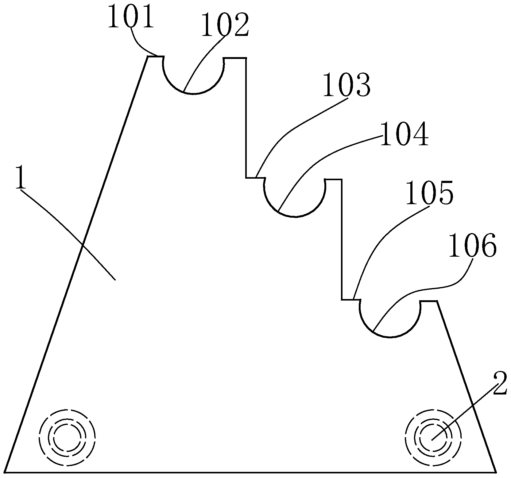
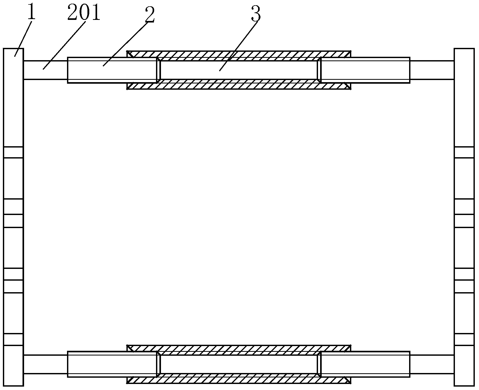
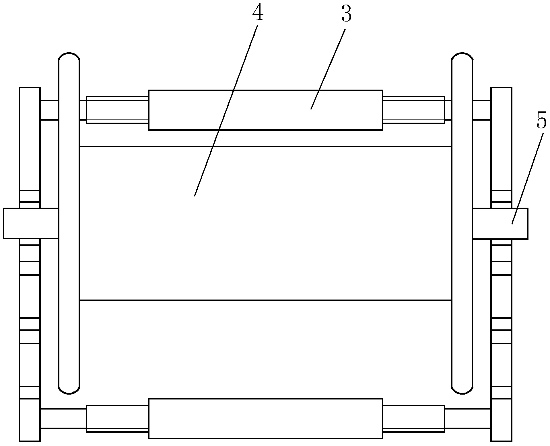
[0016] like Figure 1 to Figure 4 As shown, a width-adjustable reel support includes a side plate 1, the left and right sides of the side plate 1 are hypotenuses, and the upper end of the side plate 1 is provided with a stepped surface to target different diameters of the reel 4. Adopting different heights of step surfaces to support, it is beneficial to control the center of gravity of the reel 4 and improve the stability of the support; No. 1 arc groove 102 is provided on the No. 1 step 101 of the step surface, and No. 1 arc groove 102 is provided on the No. 2 step 103 of the step surface. No. two arc grooves 104 are arranged, and No. three arc grooves 106 are arranged on the third step 105 of the step face. Stability in the arc grooves. In a...


PUM


Abstract

The invention relates to a winding drum support with an adjustable width. The winding drum support with the adjustable width comprises side plates, wherein both the left side and the right side of each side plate are bevel edges, a step surface is arranged at the upper end of each side plate, a first arc groove is formed in a first step of each step surface, a second arc groove is formed in a second step of each step surface, a third arc groove is formed in a third step of each step surface, a screw is welded to the left bottoms of the inner sides of the side plates, a screw is welded to the right bottoms of the inner sides of the side plates, the screws are sleeved with sleeves, the length of each sleeve is larger than twice the length of the corresponding screw, internal threads are arranged on the inner side of each sleeve, and the other end of each sleeve is connected to the screw at the corresponding position of the other side plate. According to the winding drum support with the adjustable width, due to the fact that the width is adjustable, the support can be used for supporting winding drums of different types in a classified mode; due to the fact the two side plates are directly supported by the ground, the defect that breakage occurs easily due to the adoption of a cantilever supporting method is overcome; due to the fact that all the arc grooves in the upper ends of the side plates are in contact with extending-out shafts of winding drums, the phenomenon that the winding drums still idle for a long time after the halt is avoided, unnecessary waste is reduced, and the winding drums can be supported more firmly and more reliably.

Description

technical field [0001] The invention relates to the technical field of cable heat treatment equipment, in particular to a width-adjustable reel support. Background technique [0002] In the manufacturing process of cables, there is a process of wrapping a layer of insulation around the cable wires. The cable wires are generally copper wires or aluminum wires. These metal wires are wound on the reel before wrapping the insulation layer. The barrel is supported by a stand. The metal wire is untied from the reel under the action of pulling, and drives the reel to rotate on the support at the same time. [0003] At present, the main structure of this type of support is as follows: the reel is placed on two conical blocks, the conical block at one end is fixed on the lead screw that controls the left and right movement of the reel, and the other end of the lead screw is connected with a screw that adjusts the height of the lead screw. The device, the conical block at the other ...

Claims


Application Information

Patent Timeline
Patent Type & Authority Applications(China)
IPC IPC(8): B65H54/54B65H54/72
Inventor 胡宏权
Owner ANHUI YASHEN CABLE GRP
Learn More