Decompression and shock absorption structure between ballast bed and ground beam

A ballast bed and ground beam technology, applied in the field of decompression and shock absorption structures, can solve the problems such as the adverse effects of the normal use of the vehicle vibration upper structure, and achieve the effects of simple and easy construction methods, reduced pressure, and reduced production materials

Active Publication Date: 2015-08-12
TUS DESIGN GRP CO LTD +1
View PDF7 Cites 0 Cited by
  • Summary
  • Abstract
  • Description
  • Claims
  • Application Information

AI Technical Summary

Problems solved by technology

Moreover, the ballast bed is directly pressed on the ground beam, and its vehicle vibration also has an adverse effect on the normal use of the superstructure

Method used


Image

  • Decompression and shock absorption structure between ballast bed and ground beam

Examples


Embodiment

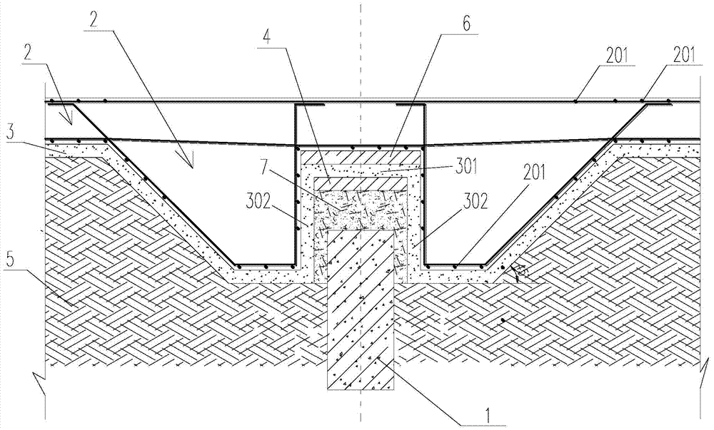
[0023] Example: figure 1 A specific embodiment of the decompression and shock absorption structure between the ballast bed and the ground beam of the present invention is shown, which includes the ground beam 1, and the backfill layer 5 of the ballast bed base (usually earth and rock materials), concrete Cushion 3 and ballast bed bottom 2, wherein ballast bed base backfill layer 5, concrete cushion 3 and ballast bed bottom 2 are all part of the ballast bed, ballast bed bottom 2 is a reinforced concrete structure, and concrete cushion 3 is made of C15 concrete material.

[0024] The key improvement of this embodiment is: the first vibration isolation plate 4 next to the bottom of the concrete cushion 3 is arranged directly above the ground beam 1, and the first vibration isolation plate 4 and the concrete cushion 3 All are separated from the ground beam 1 by a certain gap, and a loose soil backfill layer 7 is arranged in the gap.

[0025] Because in this embodiment, there is n...


PUM


Abstract

The invention discloses a pressure reduction and shock absorption structure between a ballast bed and a ground beam. The pressure reduction and shock absorption structure comprises the ballast bed and the ground beam. The ballast bed comprises a ballast bed base backfill layer, a concrete cushion and a ballast bed bottom plate which are sequentially arranged from bottom to top, a first vibration isolation plate which is adjacent to the bottom of the concrete cushion is arranged right above the ground beam, the first vibration isolation plate and the concrete cushion are respectively separated from the ground beam by a certain gap, and the gap is filled with a loose soil backfill layer. The pressure reduction and shock absorption structure between the ballast bed and the ground beam has the advantages that the pressure which is applied by the ballast bed on the ground beam can be effectively reduced, and shock on the ground beam and an upper structure connected with the ground beam due to vehicles which run on the ballast bed can be weakened.

Description

technical field [0001] The invention relates to a decompression and shock absorption structure between a ballast bed and a ground beam. Background technique [0002] At present, with the development and construction of a large number of depots and superstructures in China, in order to meet the various requirements of the depot track bed in terms of differential settlement control and upper shock isolation, the ballast bed is required to be separated from the superstructure. [0003] However, according to the existing seismic codes and other regulations, it is required to set tie-in ground beams between the pile caps of the superstructure (the upper structure is connected to the tie-in ground beams), and the span of the ground beams is large (if there are two roads, the span often above 12m). In this way, if the ground beam bears the load of the ballast bed, the section of the ground beam must be made very large. Moreover, the ballast bed is directly pressed on the ground b...

Claims


Application Information

Patent Timeline
Patent Type & Authority Patents(China)
IPC IPC(8): E01B1/00
Inventor 徐文希张敏胡恒
Owner TUS DESIGN GRP CO LTD
Why Eureka
Try Eureka