Container having liquid detecting function

a technology of liquid detection and container, which is applied in the direction of level indicators, instruments, printing, etc., can solve the problems of insufficient detection accuracy of ink cartridges, inability to detect ink cartridges, and high manufacturing costs of ink cartridges, so as to reduce the effect of vibration received, enhance detection sensitivity, and enhance detection accuracy

Inactive Publication Date: 2006-07-13
SEIKO EPSON CORP
View PDF5 Cites 18 Cited by
  • Summary
  • Abstract
  • Description
  • Claims
  • Application Information

AI Technical Summary

Benefits of technology

[0011] An advantage of the invention is to provide a container having a liquid detecting function, which can be little affected by the wave motion of ink or the bubbles in the ink to enhance the accuracy of detection.
[0012] Another advantage of the invention is that it provides a liquid sensor capable of reliably determining whether liquid exists and a liquid container including the liquid sensor. The existence of liquid is determined by simplifying a vibration mode to enhance detection sensitivity and further reducing an effect of the vibration received from liquid.
[0013] (1) In an illustrative, none-limiting embodiment, a container includes: a container body having a sending passage for sending out a liquid stored therein; a buffer chamber disposed in the vicinity of the end of the sending passage; and a sensor unit disposed to face on the buffer chamber. Here, the sensor unit has a sensor chip and the sensor chip includes: a sensor cavity communicating with the buffer chamber; a vibration plate closing an opening side of the sensor cavity opposite to the side communicating with the buffer chamber; and a piezoelectric element that is disposed on a surface of the vibration plate opposite to the surface facing the sensor cavity, emits a vibration wave to the sensor cavity and the buffer chamber through the vibration plate, receives a reflected wave returning from the buffer chamber, and converts the reflected wave into an electrical signal. Preferably, a compliance value of the buffer chamber defined as easiness in capacity variation of the buffer chamber is set to be at least ten times as large as the compliance value of the sensor cavity.
[0014] (2) The container according to (1), wherein the wall surface of the buffer chamber opposed to the vibration plate is opened, the opening is closed with a seal film having flexibility, the compliance value of the buffer chamber is given by elasticity of the seal film, and the compliance value of the sensor cavity is given by elasticity of the vibration plate.
[0015] (3) The container according to (2), wherein the buffer chamber includes two buffer chambers of an upstream buffer chamber and a downstream buffer chamber adjacent to each other with a partition wall therebetween, the upstream portion of the upstream buffer chamber communicates with the upstream side of the sending passage and the downstream portion of the upstream buffer chamber communicates with the sensor cavity through an upstream communication passage, the upstream portion of the downstream buffer chamber communicates with the sensor cavity through a downstream communication passage and the downstream portion of the downstream buffer chamber communicates with the downstream side of the sending passage, and a liquid flows in the upstream buffer chamber from the upstream side of the sending passage, enters the sensor cavity through the upstream communication passage, passes through the downstream communication passage and the downstream buffer chamber from the sensor cavity, and then is discharged to the downstream side of the sending passage.
[0016] According to the illustrative, none-limiting embodiment, since the buff chamber is provided in the vicinity of the end of the sending passage for sending out a liquid, the sensor unit is disposed to face on the buffer chamber, the sensor chip of the sensor unit emits the vibration wave to the buffer chamber, and the sensor unit detects the liquid inside the buffer chamber or the sensor cavity on the basis of the reflected wave returning to the sensor cavity from the buffer chamber, it is possible to detect the amount of remaining liquid under the condition that it is little affected by the wave motion of the liquid or the bubbles in the liquid.

Problems solved by technology

However, the management method, in which the number of ejected ink droplets or the amount of ink is integrated in software to calculate the amount of consumed ink, has the following problems.
However, in consideration of the time when errors in the amount of consumed ink due to the variation are accumulated, the ink cartridge is filled with the ink together with margin ink.
However, there are drawbacks in that kinds of ink to be detected are limited and a seal structure for an electrode becomes complicated, because detection of an ink level relies on conductivity of ink.
Therefore, manufacturing cost of the ink cartridge runs up.
Further, since two electrodes need to be mounted, the number of manufacturing processes is increased, thereby increasing the manufacturing cost.
In the technique disclosed in Patent Document 1, since the cavity of the sensor unit is allowed to directly face an ink storage chamber of the cartridge, the sensor unit can be easily affected by bubbles mixed into the ink or noises such as a wave motion of the ink, thereby decreasing accuracy of detection.

Method used


Image

  • Container having liquid detecting function
  • Container having liquid detecting function
  • Container having liquid detecting function

Examples


second embodiment

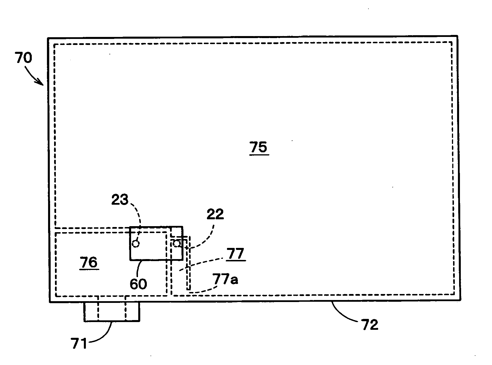
[0189]FIG. 9 shows the ink cartridge according to the present invention.

[0190] In an ink cartridge 70A, a projecting portion 76a projecting upward is formed in the upper portion of a sub reservoir chamber 76 formed inside a container body 72. Also, the inflow opening 23 of the liquid sensor 60 is disposed in the position corresponding to the projection portion 76a to communicate with the projecting portion 76a of the sub reservoir chamber 76. The rest of the present embodiment is the same as the first embodiment, so that like numerals are attached to the same portions. Further, the present embodiment also takes the same effect as the first embodiment.

third embodiment

[0191]FIGS. 10 and 11 show a liquid sensor 60A according to the present invention.

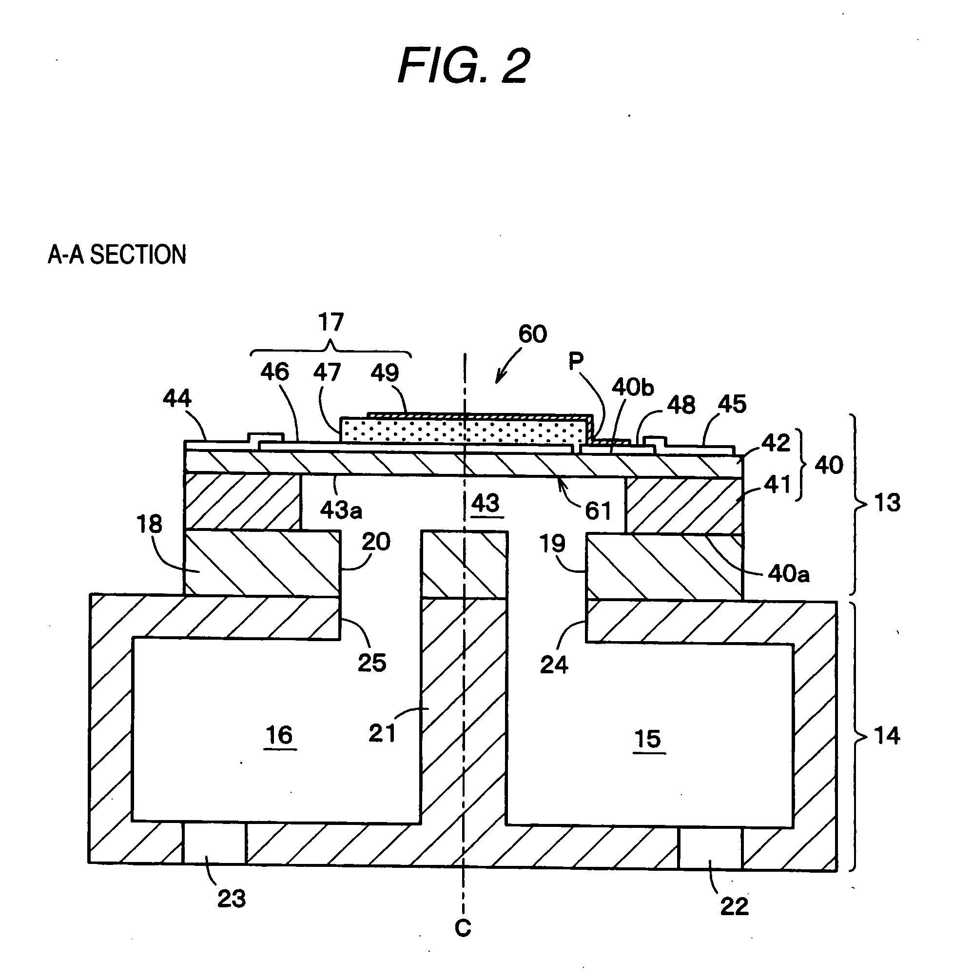
[0192] In the liquid sensor 60A, a flow path forming base portion 50, which is laminated and joined to the a first surface 40a of a vibration cavity forming base portion 40, is formed with a flow path plate 51 and an exit / entrance plate 52 laminated and joined to each other.

[0193] The flow path plate 51 of the flow path forming base portion 50, is formed with ink supply path (a liquid supply path) 19A for supplying ink to be sensed into a cavity 43 and an ink discharge path (a liquid discharge path) 20A for discharging ink to be sensed from the cavity 43. Also, the exit / entrance plate 52 is formed with an entrance 53b of the ink supply path 19A and an exit 54b of the ink discharge path 20A. Further, the entrance 53b of the ink supply path 19A and the exit 54b of the ink discharge path 20A are disposed out of the region corresponding to the cavity 43.

[0194] According to the present embodiment, the exi...

fourth embodiment

[0195] Hereinafter, an ink cartridge having a liquid detecting function (a container having a liquid detecting function) according to the present invention will be described with reference to the drawings.

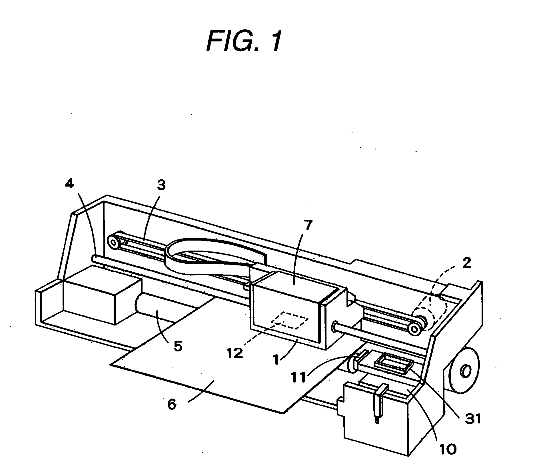
[0196]FIG. 12 shows a schematic structure of an inkjet printer (liquid jetting apparatus) employing an ink cartridge according to an embodiment of the present invention. In FIG. 12, reference numeral 1 denotes a carriage. The carriage 1 is guided to a guide member 4 through a timing belt 3 which is activated by a carriage motor 2 and reciprocates in an axis direction of a platen 5.

[0197] An inkjet printing head 12 is mounted on the side of the carriage 1 facing a printing paper 6 and an ink cartridge 100 for supplying ink to the printing head 12 is detachably mounted thereon.

[0198] In a home position (the right side in FIG. 12) which is a non-printing region of the printer, a cap member 13 is disposed. When the printing head 12 mounted on the carriage 1 moves to the home position...


PUM


Abstract

A container having a liquid detecting function includes a cartridge case 101 having a sending passage for sending out a liquid stored therein, buffer chambers 122 and 123 disposed in the vicinity of the end of the sending passage, and a sensor unit 200 disposed to face on the buffer chambers. A sensor chip 230 provided in the sensor unit includes a sensor cavity 233 communicating with the buffer chambers, a vibration plate 233 closing an opening side of the sensor cavity opposite to the side communicating with the buffer chambers, and a piezoelectric element 234 which is disposed on the surface of the vibration plate opposite to the surface facing the sensor cavity, emits a vibration wave to the sensor cavity and the buffer chambers through the vibration plate, receives a reflected wave returning from the buffer chambers through the vibration plate, and then converts the reflected wave into an electrical signal. The compliance values of the buffer chambers 122 and 123 are set to be ten times greater than the compliance value of the sensor cavity.

Description

TECHNICAL FIELD [0001] The present invention relates to a container having a liquid detecting function (mainly a residual ink detecting function) which applies to a liquid jetting apparatus such as an inkjet printer. BACKGROUND ART [0002] As a representative example of a conventional liquid jetting apparatus, there is known an inkjet printer including an inkjet printing head for printing an image. Examples of other liquid jetting apparatuses can include an apparatus including a color-material jetting head which is used for manufacturing a color filter of a liquid crystal display or the like, an apparatus including an electrode-material (conductive paste) jetting head which is used for forming an electrode of an organic EL display, a field emission display (FED), or the like, an apparatus including a living-organic-material jetting head which is used for manufacturing a biochip, and an apparatus including a sample jetting head as a precision pipette. [0003] In the inkjet printer whic...

Claims


Application Information

Patent Timeline
Patent Type & Authority Applications(United States)
IPC IPC(8): B41J2/195
CPCB41J2/17566G01F23/296G01F23/22B41J2/17509B41J2/17513B41J2/17553
Inventor ZHANG, JUNHUAKATAKURA, TAKAHIROKATSUMURA, TAKAYOSHI
Owner SEIKO EPSON CORP
Why Eureka
Try Eureka