Hydraulic pressure suspension polishing method and device thereof

A polishing device and hydraulic pressure technology, applied in the direction of grinding drive device, grinding automatic control device, grinding/polishing equipment, etc., can solve the problem that the processing efficiency cannot meet the production needs, the processing efficiency is difficult to meet the requirements, the speed of the polishing disc, etc. Low-level problems, to achieve the effect of high transmission efficiency and processing efficiency, strong anti-seismic ability, and good platform stability

Active Publication Date: 2016-05-04
ZHEJIANG UNIV OF TECH
View PDF6 Cites 18 Cited by
  • Summary
  • Abstract
  • Description
  • Claims
  • Application Information

AI Technical Summary

Problems solved by technology

Traditional non-contact polishing has less damage to the surface, the surface lattice of the workpiece is complete after processing, and the surface shape accuracy is high, but the processing efficiency is often difficult to meet the requirements
For example, dynamic pressure float-off polishing utilizes the wedge effect to make the workpiece float off the surface of the polishing disc to realize polishing processing, but the speed of the polishing disc is low, and the processing efficiency cannot meet the production needs; although the elastic launch process directly drives the polishing tool by the motor to achieve high speed Under the polishing, the processing efficiency is greatly improved, but there are problems such as uneven processing and serious wear of processing tools.

Method used


Image

  • Hydraulic pressure suspension polishing method and device thereof
  • Hydraulic pressure suspension polishing method and device thereof
  • Hydraulic pressure suspension polishing method and device thereof

Examples


Embodiment Construction

[0022] The present invention will be further described below in conjunction with accompanying drawing:

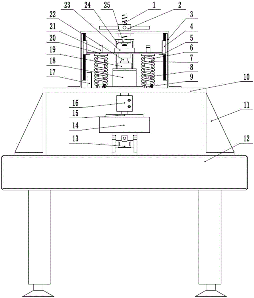
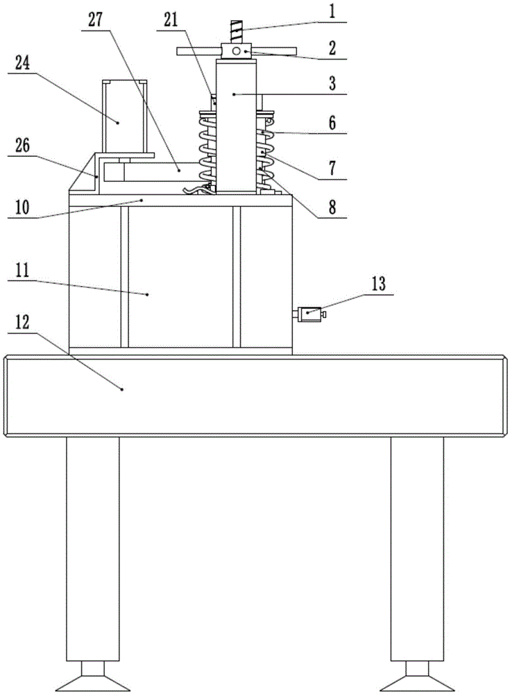
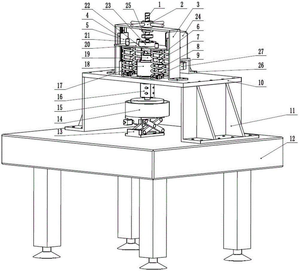
[0023] Such as Figure 1-7 As shown, the present invention includes a polishing disc 15, a hydraulic suspension device, a lifting device and a supporting device. The surface of the polishing disc 15 is divided into several basic units, and each basic unit surface includes Workpiece patch area, wedge-shaped area, reservoir and constraint boundary; Described supporting device comprises marble platform 12, base plate 10, side plate 11 and support frame 3, and support frame 3 is fixed on the described base plate 10, and described base plate 10 Supported on the marble platform 12 by the side plates 11 on both sides; The hydrodynamic suspension device includes a polishing disc 15, a ball spline shaft 22, a shaft sleeve 19, a servo motor 24, a balance plate 20, a support seat 23 and multiple groups of gravity overcoming mechanisms, and the ball spline shaft 22 sets 19 is install...


PUM


Abstract

The invention discloses a hydraulic pressure suspension polishing method and a device thereof. A servo motor and a synchronous pulley drive a shaft sleeve and a ball spline shaft so as to directly drive a polishing disk to rotate at high speed, and the processing efficiency is improved. A wedge groove is formed in the polishing disk pasted with a workpiece, and a wedging effect is formed at high speed and in small gap, so that the polishing disk drives the ball spline shaft to float upwards along the shaft sleeve, and uniform non-contact polishing is realized. A bottom container is lifted through an electric lifting platform to realize initial positioning. A force measuring sensor is mounted at the top and is used for positioning a cutter between the polishing disk and the container to ensure the reliability of positioning. The spline shaft is connected with a balance plate together through a supporting seat, and four groups of springs are arranged between the balance plate and a bottom plate and are used for overcoming the gravity of a polishing component. A laser displacement sensor mounted on the bottom plate is used for measuring the distance of floating up or down of the balance plate in the polishing process. An electrical vortex sensor and a pressure sensor are mounted at bottom container and are used for detecting the size of a polishing gap and hydraulic pressure.

Description

technical field [0001] The invention relates to the field of non-contact polishing, in particular to a hydrodynamic suspension polishing method and a device thereof. Background technique [0002] With the rapid development of new technologies, the quality requirements of products are constantly improving. As the most important means of preparing workpieces with high surface quality, non-contact polishing technology has received more and more attention today. Non-contact polishing, as the name implies, is a non-contact state between the workpiece and the polishing tool. Since there is no contact, the friction and contact heat transfer between them can be ignored. Traditional non-contact polishing has less damage to the surface, the surface lattice of the workpiece is complete after processing, and the surface shape accuracy is high, but the processing efficiency is often difficult to meet the requirements. For example, dynamic pressure float-off polishing utilizes the wedge ...

Claims


Application Information

Patent Timeline
Patent Type & Authority Applications(China)
IPC IPC(8): B24B1/00B24B49/00B24B41/00B24B47/12B24B51/00
CPCB24B1/00B24B41/007B24B47/12B24B49/00B24B51/00
Inventor 文东辉孙白冰金明生王扬渝章少杰
Owner ZHEJIANG UNIV OF TECH
Why Eureka
Try Eureka