Eureka AIR delivers breakthrough ideas for toughest innovation challenges, trusted by R&D personnel around the world.

Article surface morphology detection method and device

A technology of surface topography and detection method, applied in the field of surface topography detection of objects, can solve the problems of under-sampling effect, limit measurement speed, limit axial measurement accuracy, etc., so as to improve system stability, eliminate system vibration, and eliminate environmental problems. the effect of interference

Pending Publication Date: 2017-09-08
FOSHAN UNIVERSITY
View PDF9 Cites 17 Cited by
  • Summary
  • Abstract
  • Description
  • Claims
  • Application Information

AI Technical Summary

Problems solved by technology

At present, although a variety of numerical phase unwrapping methods have been proposed, these methods have certain problems, such as complex and time-consuming calculations, and are affected by noise and undersampling, especially when the phase difference between two adjacent points exceeds π, Unable to restore true phase
The principle of phase unwrapping is to perform phase unwrapping by comparing the phase difference between two adjacent points based on the continuity of the phase. In principle, when the phase difference between two adjacent points is greater than π, the true phase cannot be restored correctly. , which limits the scope of application of the interferometric
SWLI can measure the absolute optical distance without the phase wrapping problem, but for each detection point, axial scanning is required, the demodulation accuracy of the interference fringe and the axial scanning accuracy limit the axial measurement accuracy, and the use of axial scanning also limited measurement speed

Method used


Image

  • Article surface morphology detection method and device
  • Article surface morphology detection method and device
  • Article surface morphology detection method and device

Examples


Embodiment Construction

[0038] The technology will be further described below in conjunction with the accompanying drawings.

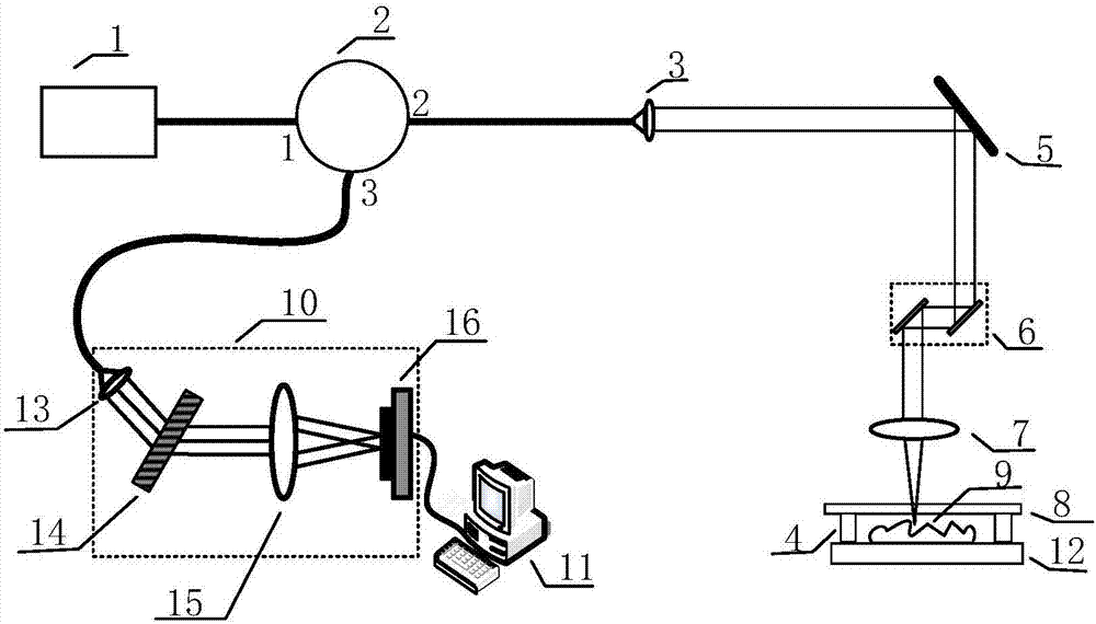
[0039] The object surface topography detection device includes: a low-coherence light source 1, a spectrometer, a three-terminal circulator 2, a first lens 3, a mirror 5, an x-y scanning galvanometer 6, a second lens 7 and a sample stage 12. The light emitted by the low-coherence light source 1 enters through the port 1 of the three-terminal circulator 2, and the light coming out of the port 2 of the three-terminal circulator 2 is collimated by the lens 3 and then hits the reflector 5, and the light after changing the direction hits x-y The x vibrating mirror of the scanning vibrating mirror 6 is shot from the x vibrating mirror to the y vibrating mirror of the x-y scanning vibrating mirror 6, and the light passing through the y vibrating mirror is focused by the second lens 7 onto the surface of the sample 9 to be measured, and passed through the scanning vibrating mirror 6 ...


PUM


Abstract

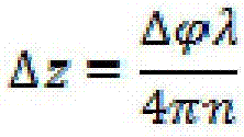
An article surface morphology detection method disclosed by the present invention comprises the following steps that (1) the low-coherence light rays irradiate in from a port 1 of a three-end circulator, irradiate out from a port 2, irradiate in from an x galvanometer in an x-y scanning galvanometer after being collimated by a first lens, and irradiate out from a y galvanometer;(3) the irradiated out light rays are focused by a second lens and then are divided into two parts of light rays by a light splitter, one part of the light rays are reflected from the undersurface of a glass as the reference light, and the other part of light rays penetrate the glass and then irradiate to the surface of a sample to be reflected as the sample light; (4) the two parts of light rays are returned in a common light path, are gathered to the y galvanometer of the scanning galvanometer via the second lens, irradiate in the x galvanometer via the y galvanometer, and then are irradiate out; (5) the light rays are gathered by the first lens to enter the port 2 of the three-end circulator, and then irradiate out from a port 3; (6) the light rays irradiated out from the port 3 enter a spectrograph, and the spectrograph transmits the data to a computer; (7) the scanning galvanometer scans the sample point by point; (8) the computer calculate the phase difference of the adjacent positions and the depth difference delta Z, thereby obtaining the final quantitative distribution situation of the surface morphology of the sample.

Description

[0001] Technical field: [0002] The invention relates to a method and a device for detecting surface topography of an article. [0003] Background technique: [0004] Microscopic surface topography detection has very important application value in industrial product testing, machinery manufacturing, electronics industry and other fields. With the development of modern electronics industry, optical micromachining and micro-electromechanical technology, the requirements for microscopic surface precision are becoming more and more High, the quality of surface topography has become one of the key factors to ensure and improve the performance, quality and life of mechanical, electronic and optical systems. In recent decades, many new technologies and methods have emerged in the field of microscopic surface topography measurement at home and abroad, which have continuously improved the measurement accuracy, and have entered the nanometer or even sub-nanometer scale from the micromet...

Claims


Application Information

Patent Timeline
IPC IPC(8): G01B11/24
CPCG01B11/2441
Inventor 张潞英周红仙
Owner FOSHAN UNIVERSITY
Why Eureka
Eureka Blog
Learn More