Impact tool

a technology of impact tool and tool holder, which is applied in the direction of manufacturing tools, percussive tools, portable drilling machines, etc., can solve the problems of inability to ensure the required wear resistance, and the inability to break the connection between the locking member and the tool holder, so as to improve the ease of assembly, reduce the vibration of the impact tool, and avoid the effect of the impact tool

Active Publication Date: 2009-09-24
MAKITA CORP
View PDF14 Cites 19 Cited by
  • Summary
  • Abstract
  • Description
  • Claims
  • Application Information

AI Technical Summary

Benefits of technology

[0020]According to a further embodiment of the invention, the first receiving portion comprises a stepped member having a protrusion extending forward from its radially outer edge and is held in contact with the radially outward portion of the second elastic element via the protrusion. The “protrusion” in this invention typically comprises the protrusion which is continuously formed in the circumferential direction of the tool bit, but it also suitably includes the protrusion which is discontinuously formed in the circumferential direction of the tool bit. In this invention, with the above-described construction, the first receiving portion can transmit an impact to the radially outward portion of the second elastic element via its protrusion, while avoiding interference with the second receiving portion which is held in contact with the radially inward portion of the second elastic element. Further, when the second receiving portion is formed, for example, by the tool holder for holding the tool bit, interference with the tool holder can be avoided. Therefore, even if the first and second elastic elements are installed under a pre-load, the tool holder has no resistance. Therefore, this construction does not affect the operability in rotating the tool holder in the circumferential direction together with the tool bit in order to position the tool bit in its circumferential direction.
[0021]According to a further embodiment of the invention, the stepped member having the protrusion is disposed on the front and rear sides of the first elastic element. The front and rear stepped members have the same shape and are disposed in symmetry on the both sides of the first elastic element. With such construction, the front and rear stepped members can be common parts. Therefore, proper installation of the front and rear stepped sleeves is ensured, so that ease of assembly can be improved.
[0022]Some impact tools have an idle driving prevention mechanism of such a type that prevents the striker from repeating idle driving movement by holding the striker in the forward position when the striker is further moved forward beyond the striking position. Such an idle driving prevention mechanism includes a front bore space which is provided to prevent the idle driving movement and defined in the forward portion of the cylinder in which the striker is slidably housed, an air vent that provides communication between the outside and the inside of the front bore space, and a non-return valve that normally closes the air vent, while being pushed outward by the air escaping through the air vent when the striker moves further forward beyond the striking position within the front bore space. When the striker that slides within the cylinder moves further forward beyond the predetermined striking position of the intermediate element, air within the front bore space is compressed by the striker and pushes the non-return valve (O-ring) outward so that the air escapes to the outside through the air vent formed in the cylinder. Thereafter, when the striker tries to move back to its pre-striking position, a negative pressure is caused in the front bore space because the non-return valve prevents inflow of outside air. As a result, the striker is prevented from moving back and held in a position forward of the striking position. Thus, the striker is prevented from repeating idle driving movement. In such an idle driving prevention mechanism using a non-return valve, when the non-return valve is pushed outward by the air escaping through the air vent, the non-return valve may be displaced in the axial direction of the tool bit.
[0023]According to the invention, when this invention is applied to an impact tool having an idle driving prevention mechanism as described above, the protrusion of the rear stepped member can be disposed opposite to a side of the non-return valve in its axial direction. Therefore, when the non-return valve is pushed outward, the protrusion can prevent the non-return valve from being displaced in its axial direction, so that any problem which may be caused by displacement of the non-return valve can be avoided.
[0024]According to a further embodiment of the invention, the impact tool further includes a cylinder that houses the striker and has a rear end surface and a front end surface in the axial direction of the tool bit which are held in contact with the tool body and the first receiving portion, respectively. Further, the first and second elastic elements are installed under a predetermined pre-load, so that the cylinder is held in the axial direction of the tool bit. According to the invention, the cylinder can be held by the elastic forces of the first and second elastic elements, so that a member for holding the cylinder (O-ring) can be omitted. Further, rattling of the cylinder is suppressed, so that vibration in the impact tool can be lowered.

Problems solved by technology

Specifically, a connection between the locking member and the tool holder and a connection between the locking member and the barrel are caused to be susceptible to wear by entry of dust.
However, if the barrel is formed from lighter materials than ferrous materials, such as nonferrous metals and synthetic resins, the required wear resistance cannot be ensured.

Method used


Image

  • Impact tool
  • Impact tool
  • Impact tool

Examples


first representative embodiment

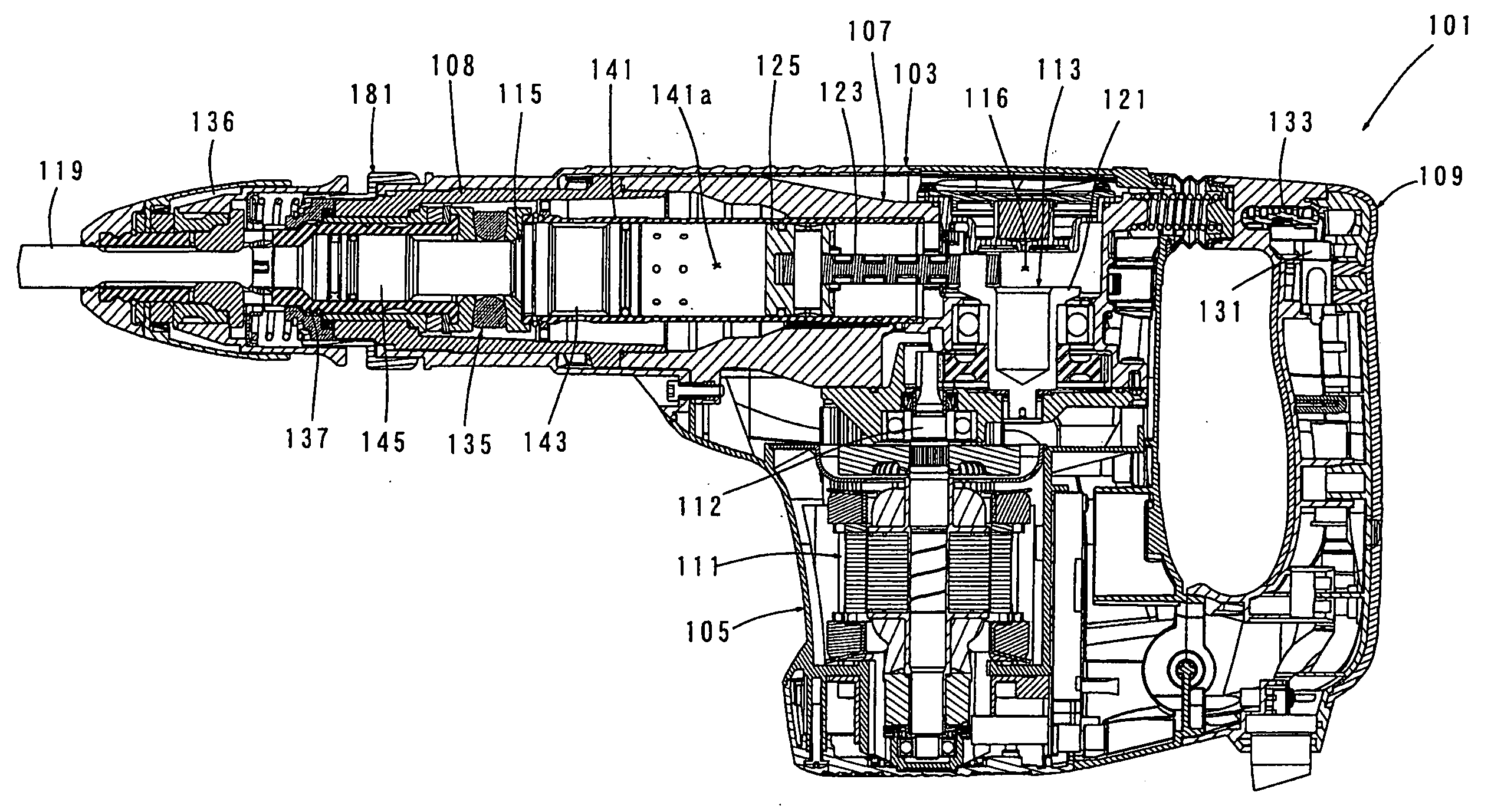
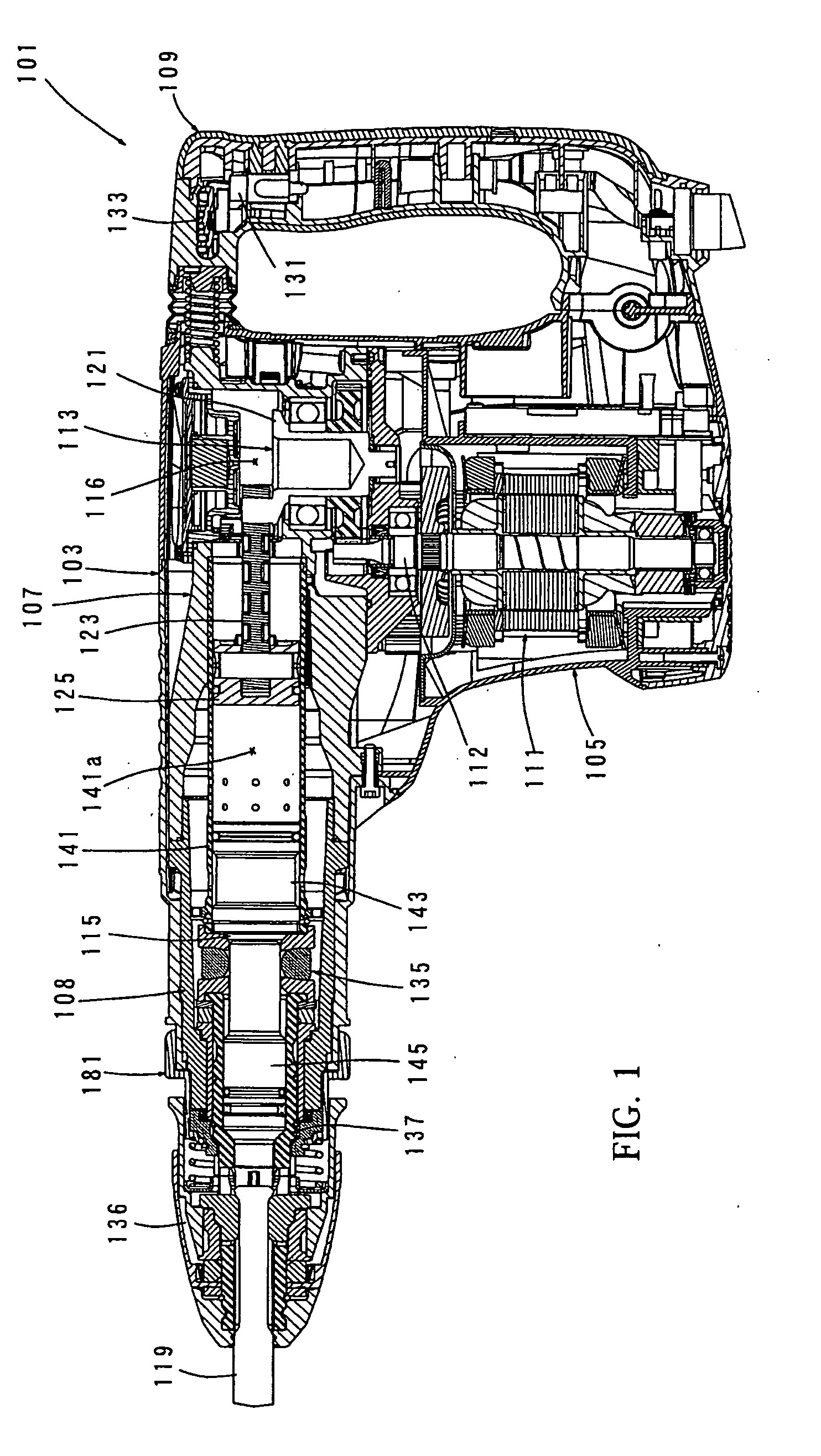
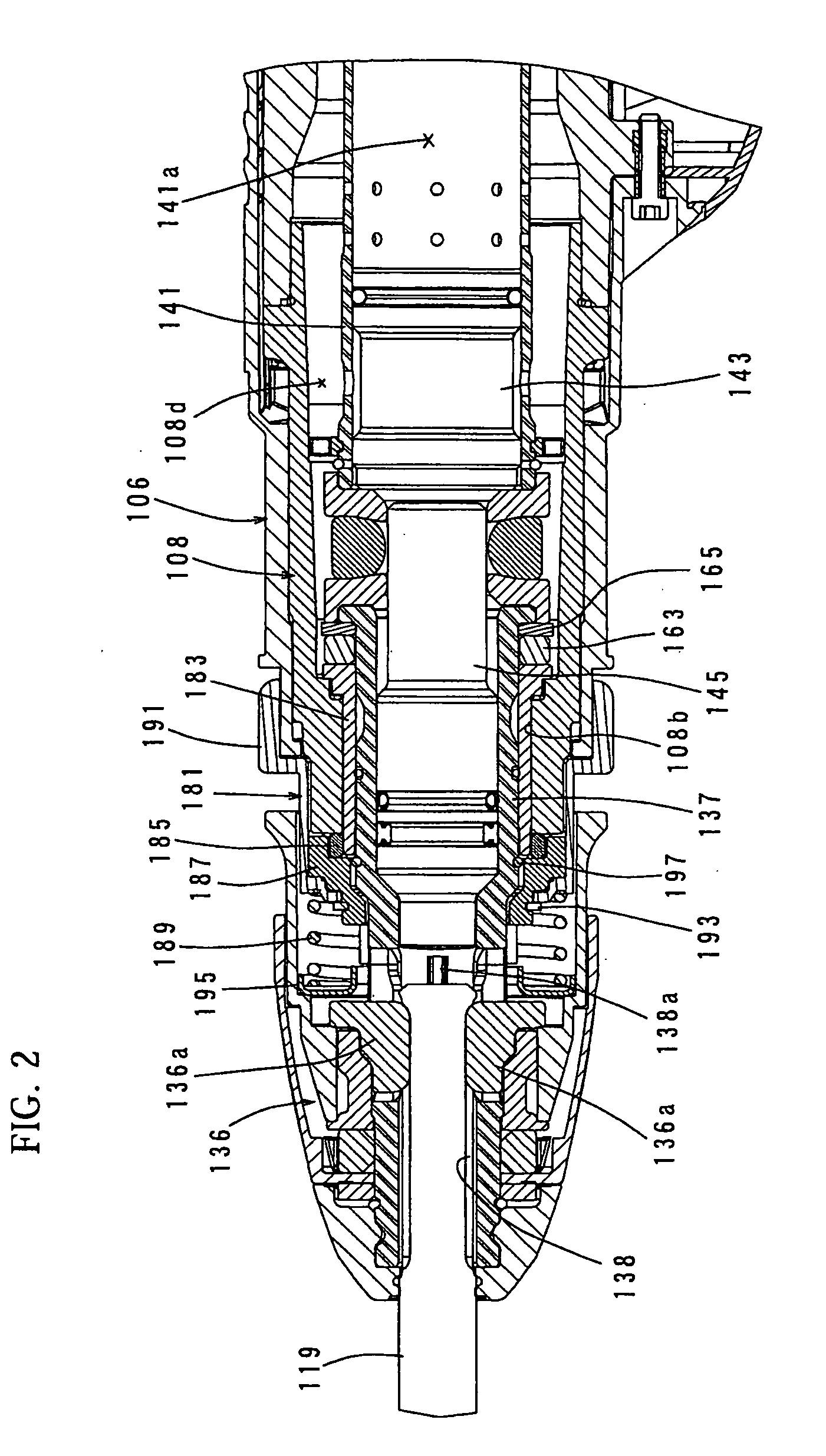
[0034]An embodiment of the invention is now described with reference to FIGS. 1 to 5. In this embodiment, an electric hammer is explained as a representative example of an impact tool according to the invention. FIG. 1 shows an entire structure of an electric hammer 101. FIG. 2 is an enlarged view showing the structure of an essential part of the electric hammer 101. FIGS. 3 to 5 are enlarged views showing the structure of an angular positioning device for positioning a hammer bit in its circumferential direction with respect to a tool body. FIG. 3 shows a rotation prevented state or positioned state of a tool holder, and FIG. 4 shows a rotation allowed state of the tool holder. FIG. 5 is a sectional view of the angular positioning device along a different line from the sectional views of FIGS. 3 and 4.

[0035]As shown in FIG. 1, the electric hammer 101 according to this embodiment includes a body 103 that forms an outer shell of the electric hammer 101, a tool holder 137 that is conn...

second representative embodiment

[0057]Second representative embodiment of the invention is now described with reference to FIGS. 6 to 9. In this embodiment, an electric hammer is explained as a representative example of an impact tool according to the invention. FIG. 6 shows an entire structure of an electric hammer 101. FIGS. 7 and 8 show the structure of an essential part of the electric hammer according to the invention. FIG. 9 is a partially enlarged view of FIG. 8. The electric hammer according to the second representative embodiment has substantially the same construction with the electric hammer. In this connection, detailed explanation of same features with the first representative embodiment is abbreviated.

[0058]When the user stops applying the pressing force against the workpiece to the hammer bit 119 in order to finish the hammering operation, the striker 143 performs an idle driving movement, or the striking movement under unloaded conditions in which no load is applied to the hammer bit 119. During th...


PUM

PropertyMeasurementUnit
striking forceaaaaaaaaaa
elasticaaaaaaaaaa
shapeaaaaaaaaaa

Abstract

It is an object of the invention to provide a technique which is effective in improving the durability of an angular positioning device of a tool bit and in reducing weight of a tool body in an impact tool. A representative impact tool includes a tool body, a lubricant sealed in the housing space, a driving mechanism, a tool holder, an angular positioning device disposed on a tip end side of the tool body and serves to fix a position of the tool bit around the axis with respect to the tool body. The angular positioning device includes first and second locking members. The first locking member is disposed between the tool body and the tool holder. The second locking member is disposed opposite to the first locking member. One end of the first locking member in the axial direction of the tool bit extends into the housing space of the tool body and is connected to the tool body within the housing space.

Description

BACKGROUND OF THE INVENTION[0001]1. Field of the Invention[0002]The invention relates to a technique of providing new and useful impact tool.[0003]2. Description of the Related Art[0004]An impact tool is provided with an angular positioning device which positions a hammer bit in its circumferential direction with respect to a tool body during hammering operation. For example, Japanese non-examined laid-open Patent publication No. 11-104974 discloses an impact tool having such an angular positioning device. The angular positioning device in the above publication is disposed in a tip end region of a barrel which forms a tool body. In the angular positioning device, a locking member is disposed between a barrel and a tool holder for holding the hammer bit. The locking member is normally connected via a spline fit with respect to the tool holder and can be connected to or disconnected from the barrel via engagement of projections and recesses. The position of the tool bit is adjusted by...

Claims


Application Information

Patent Timeline
Patent Type & Authority Applications(United States)
IPC IPC(8): B25D17/08B25D17/24
CPCB25D11/005B25D17/00B25D17/06B25D17/088B25D2211/003B25D2211/068Y10T279/17068B25D2216/0076B25D2217/0019B25D2222/24B25D2222/57B25D2250/121B25D2250/131B25D2216/0069
Inventor IWAKAMI, JUNICHIONODA, SHINJIHANAI, TAKAMASA
Owner MAKITA CORP
Why Eureka
Try Eureka