Buried type side slope drainage system and construction method thereof

A drainage system, buried technology, used in excavation, infrastructure engineering, construction, etc., can solve the problems of collapse and damage of drainage ditch, troublesome waste cleaning, insufficient drainage and other problems, to avoid damage, reduce construction costs, durable strong effect

Active Publication Date: 2014-06-25
WUHAN SURVEYING GEOTECHN RES INST OF MCC
View PDF4 Cites 24 Cited by
  • Summary
  • Abstract
  • Description
  • Claims
  • Application Information

AI Technical Summary

Problems solved by technology

[0004] In addition, there are also the following defects in the methods of building drainage ditches on the slope and digging trenches to build drainage ditches: 1. Both of the two masonry methods need to use a large amount of materials such as concrete or chip stones, and a large amount of The cost of these materials is high, which increases the cost of masonry; 2. If a small displacement occurs on the slope, when the local soil on the slope

Method used


Image

  • Buried type side slope drainage system and construction method thereof
  • Buried type side slope drainage system and construction method thereof
  • Buried type side slope drainage system and construction method thereof

Examples


Embodiment 1

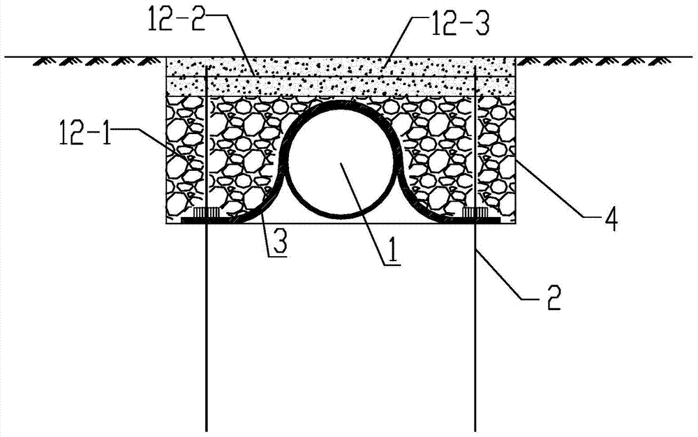
[0044] Example 1: Construction is carried out specifically for a certain filling slope. The slope is filled with geogrid reverse-wrapped woven bags layered and crushed gravel soil, and the slope is protected by spraying with hanging nets; the traditional drainage ditch is in the The masonry on the woven bag is easy to be damaged; this problem can be overcome by adopting the method of the present invention, and its specific construction steps are as follows:

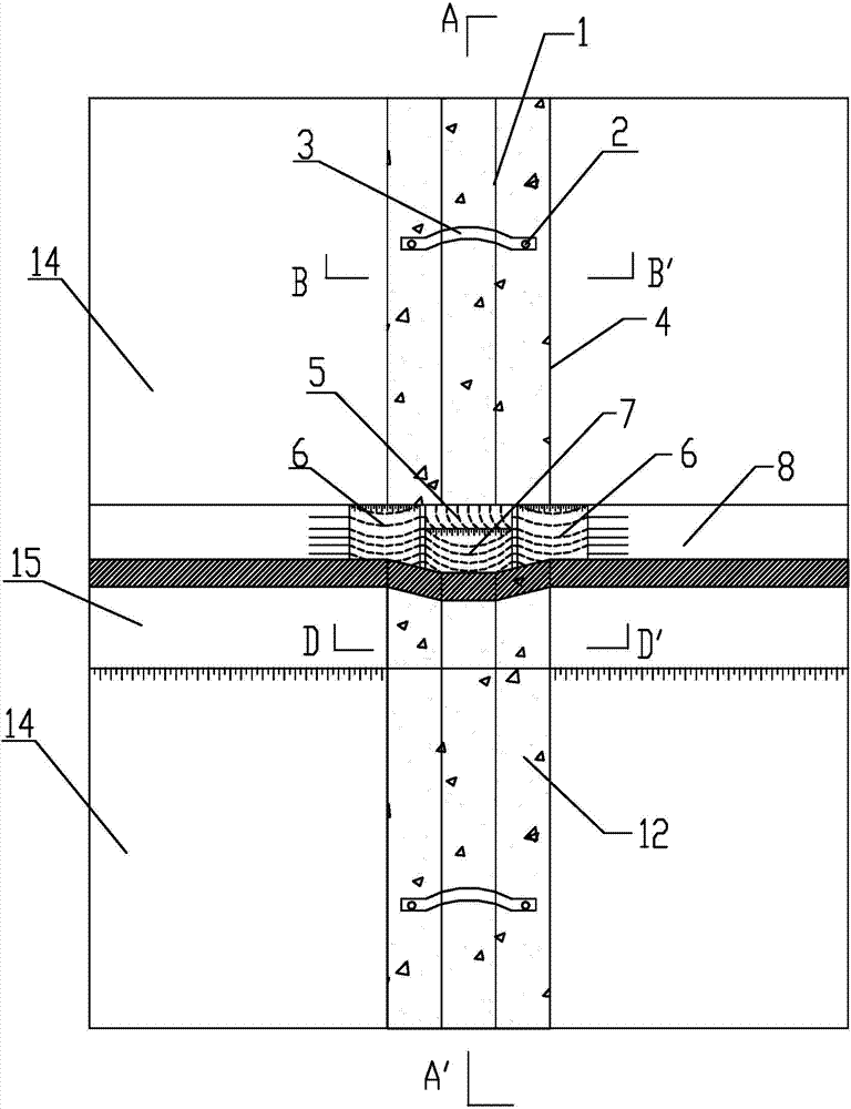
[0045] 1. Measurement and setting out: Determine the setting positions of vertical drainage ditches and horizontal drainage ditches on the slope and platform of the fill slope according to the design drawings, and calibrate the axis positions of horizontal and vertical drainage ditches according to the design;

[0046] 2. Reinforced soil construction: According to the construction process, lay geogrids and turn up the woven bags, then backfill gravel soil and carry out layered rolling. During the filling process, design ve...

Embodiment 2

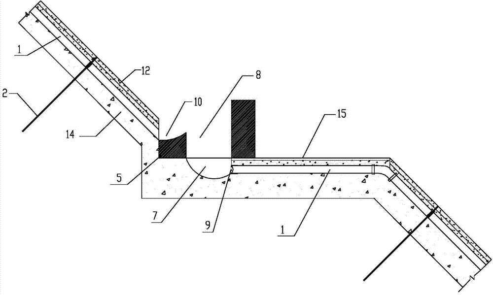
[0052] Embodiment 2: Take the excavation slope as a specific implementation. The slope is an excavation rock slope with moderately developed fissures. The slope is planned to be supported by anchor lattice beams. The use of traditional drainage ditches will destroy the continuity of the lattice beams and have a certain impact on the overall stability. This problem can be effectively solved by using this invention. The specific construction steps as follows:

[0053] 1. Slope shaping: trim the slope according to the design to form an excavated rock slope;

[0054] 2. Groove positioning and excavation: Position the horizontal and vertical drainage ditches according to the design standards, and then excavate at the position of the vertical drainage ditches to form a ditch-shaped drainage pipe pre-buried whose width and depth meet the design requirements of slope drainage groove;

[0055] 3. Lay anchor bolts: lay anchor bolts near the two sides in the pre-buried groove of the d...


PUM


Abstract

The invention provides a buried type side slope drainage system and a construction method thereof. The drainage system comprises a plurality of transverse drainage ditches and a plurality of vertical drainage ditches. The vertical drainage ditches are of drainage structures formed in the manner that after a slope is filled or dug according to a design drawing, drainage pipe pre-buried grooves are formed in the positions, corresponding to the vertical drainage ditches, of all levels of side slopes and platforms, drainage pipes are pre-buried in the drainage pipe pre-buried grooves, and protection structures are built on the upper portions of the drainage pipe pre-buried grooves. A force eliminating platform, an accumulating pond and a water collecting pond are built at the joint of the transverse drainage ditches and the vertical drainage ditches, the force eliminating platform is right opposite to water outlets of the drainage pipes in the upper level side slope, and water is led to the collecting pond and the water collecting pond in sequence and then is led into the vertical drainage pipes in the lower level side slope through the water collecting pond. According to the buried type side slope drainage system and the construction method, the constructed drainage system is buried underground, the continuity and attractiveness of side slope protection are not affected, the drainage pipes cannot be damaged by exposing and grinding, the drainage pipes are prevented from being blocked through a multi-layer filtering method, the drainage smoothness is improved, and maintaining cost is reduced.

Description

technical field [0001] The patent of the present invention relates to the field of slope drainage, and specifically relates to a buried slope drainage system and a construction method thereof which use buried drainage pipes to connect two-stage platform drainage ditches as drainage channels. Background technique [0002] An important link in slope design is the design of drainage system. The impact of water on slope stability is great, sometimes even catastrophic. If the drainage measures are not perfect, the slope may become unstable, so a reasonable and effective drainage system must be adopted. The common drainage system generally adopts the combination of horizontal drainage ditch and vertical drainage ditch. The horizontal drainage ditch is generally built as a platform row between the two slopes, and the vertical drainage ditch connects two adjacent horizontal drainage ditch longitudinally. The vertical drainage ditch and the horizontal drainage ditch intersect to for...

Claims


Application Information

Patent Timeline
IPC IPC(8): E02D19/20E02D17/20
Inventor 刘续郭培玺余火忠欧阳小良
Owner WUHAN SURVEYING GEOTECHN RES INST OF MCC
Why Eureka
Try Eureka