
Turbine device with sealing leakage flow diversion function

A leakage flow and turbine technology, applied in the field of fluid dynamics, can solve the problems of flow loss, leakage fluid, mixing, etc., and achieve the effect of eliminating the entrainment flow loss

Active Publication Date: 2015-08-12
INST OF ENGINEERING THERMOPHYSICS - CHINESE ACAD OF SCI
View PDF5 Cites 0 Cited by
  • Summary
  • Abstract
  • Description
  • Claims
  • Application Information

AI Technical Summary

Problems solved by technology

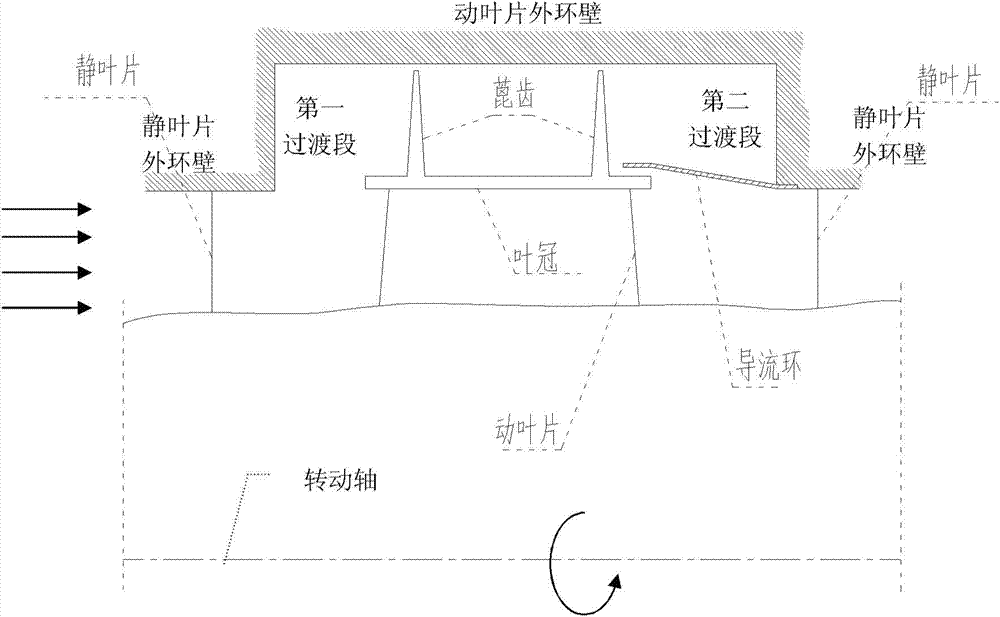
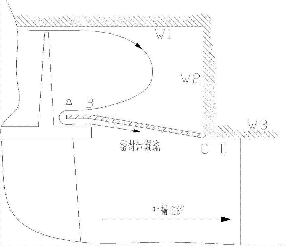
[0006] In the process of realizing the present invention, the applicant found that the non-contact seal of the prior art turbine device has the following technical defects: there is vortex dissipation driven by the main flow in the open outlet cavity of the shroud seal, and the seal leakage flow entrains part of the cascade outlet The fluid is mixed with the main flow before entering the next row of cascades in a nearly vertical direction, causing a large flow loss

Method used


Image

  • Turbine device with sealing leakage flow diversion function
  • Turbine device with sealing leakage flow diversion function

Examples


Embodiment Construction

[0018] In order to make the object, technical solution and advantages of the present invention clearer, the present invention will be described in further detail below in conjunction with specific embodiments and with reference to the accompanying drawings. It should be noted that, in the drawings or descriptions of the specification, similar or identical parts all use the same figure numbers. Implementations not shown or described in the accompanying drawings are forms known to those of ordinary skill in the art. Additionally, while illustrations of parameters including particular values ​​may be provided herein, it should be understood that the parameters need not be exactly equal to the corresponding values, but rather may approximate the corresponding values ​​within acceptable error margins or design constraints. The directional terms mentioned in the embodiments, such as "upper", "lower", "front", "rear", "left", "right", etc., are only referring to the directions of the...


PUM


Abstract

The invention provides a turbine device with a seal leakage flow guiding function. The turbine device comprises a turbine case and N turbine blade stages. The inner surface of the turbine case is provided with N blade working sections, and each blade working section comprises a static blade outer ring wall, a movable blade outer ring wall and an integral shroud sealing cavity front and back transition section. Each turbine blade stage comprises a static blade, a movable blade and a flow guiding ring, wherein the top of the movable blade is provided with an integral shroud, and labyrinths are arranged on the integral shroud, the flow guiding ring is in a circular ring shape and located on the downstream side of the movable blade, the tail ends of rear transition sections of the turbine blade stages extend toward the connecting positions of the integral shrouds and the labyrinths on the movable blades, and the edges of the inner sides are close to the turbine integral shrouds and the labyrinths but do not make contact with the turbine integral shrouds and the labyrinths. The flow guiding rings guide seal leakage flows to flow, close to the solid surface, inside a cavity formed by the inner wall of the turbine case, the labyrinths and the flow guiding rings, it is avoided that part of fluid of blade lattice main flows invades into an outlet cavity, so that entrainment losses are caused, and mixing losses of the seal leakage flows and the blade lattice main flows are reduced.

Description

technical field [0001] The invention relates to the technical field of fluid dynamics, in particular to a turbine device with the function of diversion of sealing leakage flow, which can be applied to fluid machinery such as aeroengines, gas turbines and steam turbines. Background technique [0002] Non-contact seals are indispensable components in turbomachinery power devices such as aeroengines, ground gas turbines and steam turbines, and have a non-negligible impact on the economy and reliability of the device. There is a radial gap in the non-contact seal. Under the action of the pressure difference between the inlet and outlet of the seal chamber, the seal leakage flow will inevitably occur, which will cause bypass and flow loss. [0003] In the turbine structure, considering the structural strength, in order to avoid the breakage of the turbine blades due to vibration, it is necessary to add a shroud on the top of the turbine. During the working process of the turbine...

Claims


Application Information

Patent Timeline
Patent Type & Authority Patents(China)
IPC IPC(8): F01D11/02
Inventor 张冬阳
Owner INST OF ENGINEERING THERMOPHYSICS - CHINESE ACAD OF SCI
Learn More