Quantitative liquid supply device

A technology of quantitative liquid supply and liquid feeding, which is used in quantitative devices, engine components, and engine lubrication. It can solve the problem of easy blockage of liquid supply pipelines, unbalanced torque of stator and rotor rotation, and inaccurate measurement of quantitative liquid supply devices. and other problems, to achieve the effect of shortening cycle time, expanding breadth, and improving safety

Active Publication Date: 2017-02-15
周一平
View PDF6 Cites 2 Cited by
  • Summary
  • Abstract
  • Description
  • Claims
  • Application Information

AI Technical Summary

Problems solved by technology

[0002] The measurement of the existing quantitative liquid supply device is not very accurate. The patent ZL201010154181.5 provides a metered quantitative liquid supply device. The moment of rotation on the stator and rotor is unbalanced, and the liquid supply pipe is easily blocked

Method used


Image

  • Quantitative liquid supply device
  • Quantitative liquid supply device
  • Quantitative liquid supply device

Examples


Embodiment 1

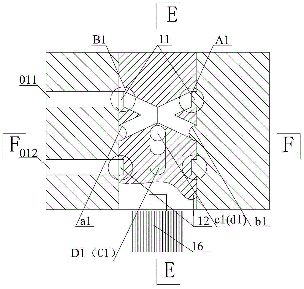
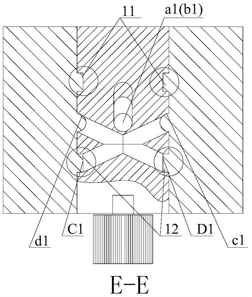
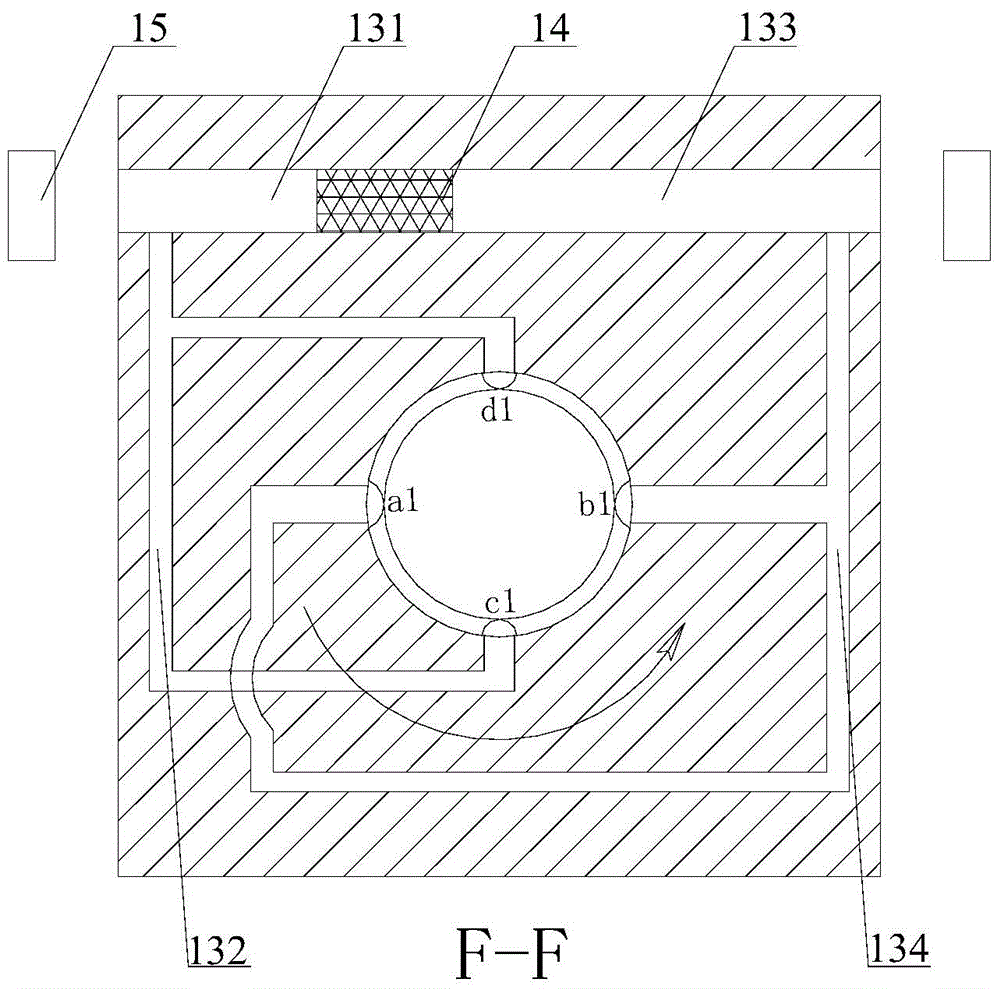
[0036] Such as Figures 1 to 9 As shown, the quantitative liquid supply device of this embodiment includes a rotating core and a stator sleeved on the rotating core, and the stator and the outer wall of the rotating core are liquid-tightly matched.

[0037]The rotating core includes a liquid circuit mechanism, and the liquid circuit mechanism includes a liquid inlet unit and a liquid outlet unit.

[0038] The liquid inlet unit includes a single liquid inlet structure, wherein the single liquid inlet structure includes a group of liquid inlet channels and a liquid inlet annular groove 11 arranged on the rotating core, and the liquid inlet channel is formed by the The rotating core is composed of two intersecting liquid inlet pipes, and the intersection point of the liquid inlet pipes is on the axis line of the rotating core, the liquid inlet annular groove is arranged around the axis line, and each of the The liquid inlet holes B1 and A1 of the liquid inlet pipe are arranged i...

Embodiment 2

[0052] Such as Figures 10 to 15 As shown, the quantitative liquid supply device of this embodiment includes a rotating core and a stator sleeved on the rotating core, and the stator and the outer wall of the rotating core are liquid-tightly matched.

[0053] The rotating core includes a liquid circuit mechanism, and the liquid circuit mechanism includes a liquid inlet unit and a liquid outlet unit.

[0054] The liquid inlet unit includes a double liquid inlet structure, and the double liquid inlet structure includes two groups of liquid inlet channels symmetrically arranged on the rotor core and a liquid inlet annular groove 21, wherein the liquid inlet channels are composed of The rotating core is composed of at least two intersecting liquid inlet pipes, and the intersection point of the liquid inlet pipes is on the axis line of the rotating core, and the liquid inlet annular groove is arranged around the axis line The liquid inlet holes A2 and B2 of each of the liquid inle...

Embodiment 3

[0070] The quantitative liquid supply device of this embodiment has been partially changed on the basis of Embodiment 2. The change is that the liquid outlet unit of this embodiment includes a double liquid outlet structure, and the double liquid outlet structure includes symmetrically arranged on the Two sets of liquid inlet passages and a liquid inlet annular groove on the rotor core, the liquid inlet passages are composed of two intersecting liquid inlet pipes on the rotor core, and the intersection point of the liquid inlet pipes is at the On the axis line of the rotating core, the liquid inlet annular groove is arranged around the axis line, the liquid inlet holes of each of the liquid inlet pipes are arranged in the liquid inlet annular groove, and the liquid inlet channels of each The liquid outlet holes are arranged on the outer wall of the rotating core, wherein the liquid inlet holes of the two corresponding liquid inlet pipes in the two groups of liquid inlet channel...


PUM


Abstract

The invention discloses a quantified liquid supply device which comprises a liquid feeding unit and a liquid drain unit. A circle of annular liquid feeding groove around the axial lead of a rotation core is arranged on the outer wall of the rotation core, a set of liquid feeding pipelines is arranged in the rotation core and is composed of at least two liquid feeding channels which are communicated with each other in a crossed mode, and the cross point of liquid feeding channels is located on the axial lead of the rotation core. Liquid inlets of all liquid feeding channels are formed in the annular groove, and liquid outlets of the liquid feeding channels are formed in the outer wall of the rotation core. A circle of annular liquid drain groove around the axial lead of the rotation core is arranged on the outer wall of the rotation core, a set of liquid drain pipelines is formed in the rotation core and is composed of at least two liquid drain channels which are communicated with each other in a crossed mode, the cross point of the liquid drain channels is located on the axial lead of the rotation core, liquid outlets of the liquid drain channels are formed in the annular groove, and liquid inlets of the liquid drain channels are formed in the outer wall of the rotation core.

Description

technical field [0001] The invention relates to a quantitative liquid supply device. Background technique [0002] The measurement of the existing quantitative liquid supply device is not very accurate. The patent ZL201010154181.5 provides a metered quantitative liquid supply device. The moment of rotation on the stator and rotor is unbalanced, and the liquid supply pipe is easily blocked. Contents of the invention [0003] In view of the above problems, the present invention provides a quantitative liquid supply device with reasonable structure and accurate measurement. [0004] In order to achieve the above purpose, the quantitative liquid supply device of the present invention includes a rotating core and a stator sleeved on the rotating core, and the outer wall of the rotating core is liquid-tightly matched with the stator, wherein [0005] The rotating core includes at least one liquid circuit mechanism, and the liquid circuit mechanism includes a liquid inlet unit ...

Claims


Application Information

Patent Timeline
Patent Type & Authority Patents(China)
IPC IPC(8): F16N27/00
Inventor 周一平
Owner 周一平
Why Eureka
Try Eureka