A transmission cavity frequency stabilization device capable of simultaneous multi-beam laser frequency stabilization

A transmission cavity and laser technology, applied in lasers, laser parts, phonon exciters, etc., can solve the problems of high cost, waste of space, complexity, etc., and achieve the effect of saving space, convenient use and reducing cost.

Active Publication Date: 2016-08-17
WUHAN INST OF PHYSICS & MATHEMATICS CHINESE ACADEMY OF SCI
View PDF4 Cites 3 Cited by
  • Summary
  • Abstract
  • Description
  • Claims
  • Application Information

AI Technical Summary

Problems solved by technology

[0021] The traditional transmission cavity frequency stabilization method can only use a set of transmission cavity and a reference laser to lock a beam of laser to be stabilized, which wastes space and is costly. It is complicated to use whether the locked laser on the transmission cavity is unlocked

Method used


Image

  • A transmission cavity frequency stabilization device capable of simultaneous multi-beam laser frequency stabilization
  • A transmission cavity frequency stabilization device capable of simultaneous multi-beam laser frequency stabilization
  • A transmission cavity frequency stabilization device capable of simultaneous multi-beam laser frequency stabilization

Examples


Embodiment 1

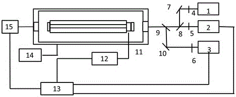
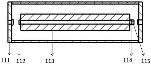
[0045] A transmission cavity frequency stabilization device that can stabilize the frequency of two lasers at the same time. figure 1 with figure 2 It can be seen that the frequency stabilization device consists of a transmission cavity 11, a reference laser 1, and two to-be-stabilized lasers of different wavelengths: the first to-be-stabilized laser 2, the second to-be-stabilized laser 3, the first lens 4, the second lens 5, and the third The lens 6, the first reflector 7, the second reflector 10, the first beam splitter 8, the second beam splitter 9, the piezoelectric controller 12, the calculation controller 13, the temperature controller 14 and the photodetector 15.

[0046] The first to be stabilized laser 2, the second lens 5, the first beam splitter 8, the second beam splitter 9, the transmission cavity 11 and the photosensitive surface of the photodetector 15 are placed in sequence; the first to be stabilized laser 2, the second lens 5 , The transmission cavity 11 and the...

Embodiment 2

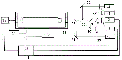
[0048] A transmission cavity frequency stabilization device that can lock the frequencies of 4 laser beams, by image 3 with figure 2 It can be seen that the frequency stabilization device consists of a transmission cavity 11, a reference laser 1, and four to-be-stabilized lasers with different wavelengths: the first to-be-stabilized laser 2, the second to-be-stabilized laser 3, the third to-be-stabilized laser 16, and the fourth to-be-stabilized laser 17. First lens 4, second lens 5, third lens 6, fourth lens 18, fifth lens 19, first mirror 7, second mirror 10, third mirror 20, fourth mirror 21 The first beam splitter 8, the second beam splitter 9, the third beam splitter 22, the fourth beam splitter 23, the piezoelectric controller 12, the calculation controller 13, the temperature controller 14 and the photodetector 15.

[0049] The first to be stabilized laser 2, the second lens 5, the first beam splitter 8, the second beam splitter 9, the third beam splitter 22, the fourth b...


PUM


Abstract

The invention discloses a transmission cavity frequency regulator capable of carrying out frequency stabilization on multiple beams of laser, and relates to the field of laser frequency stabilization. The abstract attached diagram is a structure diagram of the transmission cavity frequency regulator capable of carrying out frequency stabilization on four beams of laser. The frequency regulator is composed of a transmission cavity (11), a reference laser (1), four lasers to be stabilized with different wave lengths (2, 3, 16 and 17), lenses (4, 5, 6, 18 and 19), reflector mirrors (7, 10, 20 and 21), spectroscopes (8, 9, 22 and 23), a piezoelectric controller (12), a calculation controller (13), a temperature controller (14) and a photoelectric detector (15). The transmission cavity frequency regulator capable of carrying out frequency stabilization on the multiple beams of laser has the advantages of being capable of simultaneously locking the frequencies of the multiple beams of laser, restraining long-time drifting of the frequencies of the multiple beams of laser, being convenient to use, saving space and lowering cost, and can be widely applied to the fields needing laser frequency stabilization such as laser physics, frequency standards and quantum information.

Description

Technical field [0001] The invention relates to laser frequency stabilization technology, and more specifically to a device that uses a transmission cavity to stabilize the laser frequency. It is suitable for laser physics, frequency standard, quantum information and other fields that require laser frequency stability. Background technique [0002] In precision spectroscopy experiments, multiple lasers with stable frequency are required. The long-term drift of laser frequency needs to be less than 1MHz / h. The long-term drift of free-running lasers in the laboratory is greater than 100MHz / h due to temperature changes and vibration effects. Therefore, Need to stabilize the laser frequency. Technically, it is possible to use Fabry-Perot cavity and saturated absorption for frequency stabilization, but it is more complicated, and it is difficult to find suitable atomic and molecular spectral lines to meet the needs of frequency stabilization. The use of transmission cavity for freque...

Claims


Application Information

Patent Timeline
Patent Type & Authority Patents(China)
IPC IPC(8): H01S3/13
Inventor 商俊娟曹健崔凯枫舒华林黄学人
Owner WUHAN INST OF PHYSICS & MATHEMATICS CHINESE ACADEMY OF SCI
Why Eureka
Try Eureka