Ceramic refractory plug

A technology for refractory plugs and ceramics, applied in the field of ceramic refractory plugs, can solve the second problem that cannot be solved, can not reduce abrasion and other problems, and achieve the effects of avoiding condensation, avoiding clogging, and high gas temperature

Active Publication Date: 2016-02-03
REFRACTORY INTELLECTUAL PRORERTY GMBH & CO KG
View PDF5 Cites 0 Cited by
  • Summary
  • Abstract
  • Description
  • Claims
  • Application Information

AI Technical Summary

Problems solved by technology

In this respect, any change in the material of the stopper rod can solve the first problem, but not the second, and vice versa, any external heating of the stopper area can reduce the temperature gradient, but not the abrasion problem

Method used


Image

  • Ceramic refractory plug

Examples


Embodiment Construction

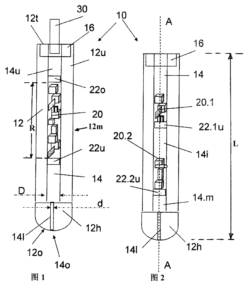
[0068] Figure 1 shows a longitudinal cross-section of a stopper rod 10 according to the invention in its working position. According to the prior art, it is made of a refractory ceramic plug body 12 shaped as a rod, comprising a substantially cylindrical main section 12m (in FIG. 1 , the upper section) and a head at its lower end. Section 12h, Head The section 12h is typically called the plug head.

[0069] The rod-shaped plug body 12 defines a central longitudinal plug axis ( figure 2 ), and includes a cylindrical gas channel 14, which extends concentrically with respect to the axis A from the upper end 12u of the plug body 12 to the plug head 12h in the plug body 12 (thus defining an inner diameter D The upper section 14u of the cylindrical gas channel 14), and extends into the plug head 12h and finally extends into the free outer surface area 12o of the plug 12h (thereby defining a cylindrical gas channel with an inner diameter d 14 lower section 14l).

[0070] At its up...


PUM

PropertyMeasurementUnit
thermal resistanceaaaaaaaaaa
particle sizeaaaaaaaaaa
lengthaaaaaaaaaa

Abstract

The present invention relates to ceramic refractory plugs (plug devices) for controlling the flow of molten metal at outlet openings of metallurgical vessels such as tundishes.

Description

technical field [0001] The present invention relates to ceramic refractory plugs (plug devices) for controlling the flow of molten metal at the outlet opening of a metallurgical vessel, such as a tundish. Background technique [0002] A general type of ceramic refractory plug consists of a rod-shaped plug body, one end of which is designed to be fixed to a corresponding lifting mechanism, while the other end is defined by a so-called plug head. The rod-shaped plug body typically has a central longitudinal axis. [0003] In steel casting, it is known to arrange such stopper rods (in many cases one-piece stopper rods) in a vertical position in order to change the transverse direction of the associated outlet opening of the corresponding metallurgical vessel by said lifting action. cross-sectional area. In this regard, any orientations disclosed hereinafter as "top", "bottom", "upper" and "lower" always refer to the vertical use position shown in the figures of the accompanyi...

Claims


Application Information

Patent Timeline
Patent Type & Authority Patents(China)
IPC IPC(8): B22D41/18
CPCB22D41/186
Inventor G.尼茨尔A.施特拉尼迈尔H-J.哈斯林格H.考夫曼
Owner REFRACTORY INTELLECTUAL PRORERTY GMBH & CO KG
Why Eureka
Try Eureka