Drum shear

A technology of shearing machine, roller type, applied in the field of application of a method, to achieve the effect of reducing the quantity

Inactive Publication Date: 2014-06-25
PRIMETALS TECH AUSTRIA GMBH
View PDF5 Cites 11 Cited by
  • Summary
  • Abstract
  • Description
  • Claims
  • Application Information

AI Technical Summary

Problems solved by technology

In the case of very thin and very rapidly moving steel strips which are to be reliably separate

Method used


Image

  • Drum shear
  • Drum shear
  • Drum shear

Examples


Embodiment Construction

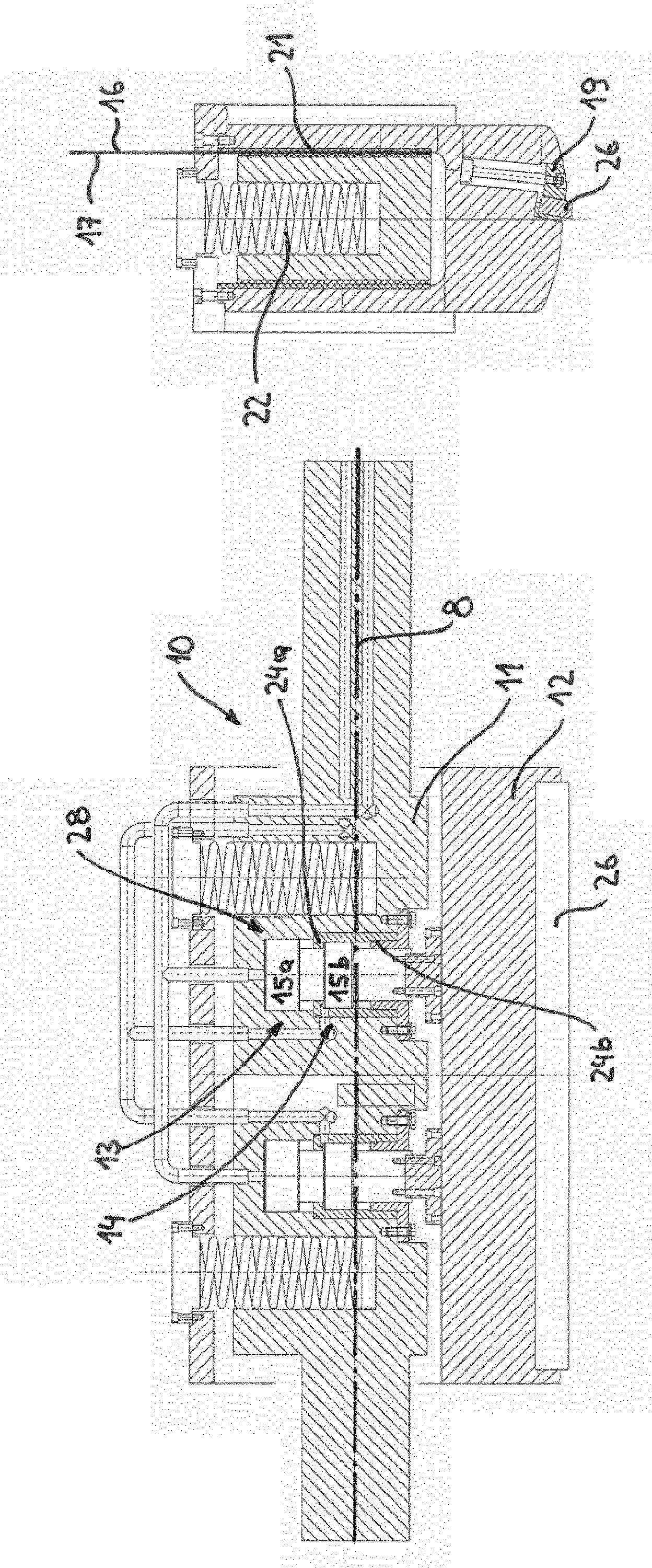
[0045] said figure 1 An exemplary embodiment of a drum shear 1 according to the invention is shown in front view. The drum shear 1 is used for transversely cutting a fast-moving thin steel strip 2 . To carry out the cut, a stroke of approximately 70 mm is performed. The double-drum shear 1 comprises an upper drum 10 and a lower drum 20 , the rotation axes 8 of which are rotatably supported in the frame 27 at a fixed distance from each other. The two cylinders 10 , 20 rotate in opposite directions with a knife 26 each. The rolling stock 2 to be sheared travels from the left to the drum shear 1 in the direction of the arrow 3, is separated at the desired moment, and is figure 1 in the schematic diagram left from the right. Typical speeds of the rolled strip 2 are 1 m / s to 20 m / s, or higher. The steel strip 2 generally has a thickness of approximately 0.5 mm to 5 mm. A knife play of no more than 30% of the strip thickness at the moment of cutting therefore requires very pre...


PUM


Abstract

The invention relates to a drum shear (1) and to a method for cross-cutting rolled stock (2) by means of the drum shear (1). The aim of the invention is to provide a drum shear (1) and a method for cross-cutting rolled stock (2) by means of the drum shear (1), by way of which the blades (26) of the drum shear (1) can be moved rapidly and in a precisely positioned manner into the cutting position. Moreover, the drum shear (1) should be of simple and robust design. The aim is achieved in that a drum shear (1) is provided in which the actuating device (28) comprises a first hydraulic cylinder (13) and a second hydraulic cylinder (14), wherein the first hydraulic cylinder (13) is arranged between the first part (11) and the second hydraulic cylinder (14), and the second hydraulic cylinder (14) is arranged between the first hydraulic cylinder (13) and the second part (12).

Description

technical field [0001] The invention relates to a drum shear for transversely cutting rolled material, such as cold-rolled or hot-rolled material, which can be configured as flat or elongated products , the drum type shearing machine comprises: [0002] two opposite rollers, said rollers being drivable by means of drive means with a peripheral speed corresponding to the translational speed of the rolling stock; [0003] Wherein, each drum has a first part and a second part, the first part is rotatably supported around a rotation axis, and the second part is loaded with a cutter; [0004] A guide is formed between the first part and the second part, so that the second part can be slidably adjusted between a starting position and a cutting position by means of an actuating device. [0005] Furthermore, the invention relates to a method for transversely cutting rolling stock by means of a drum shear having two drums and each drum having at least one knife, wherein the knife can...

Claims


Application Information

Patent Timeline
IPC IPC(8): B23D25/12
CPCB23D35/005B23D25/12
Inventor G.霍亨比奇勒C.勒纳W.佩特M.札赫迪
Owner PRIMETALS TECH AUSTRIA GMBH
Why Eureka
Try Eureka