Vibration damper with a hydraulic end stop
一种止挡部、液压端的技术,应用在具有液压端部止挡部领域,能够解决能量吸收限制等问题,达到节省材料的效果
- Summary
- Abstract
- Description
- Claims
- Application Information
AI Technical Summary
Problems solved by technology
Method used
Image

Examples
Embodiment Construction
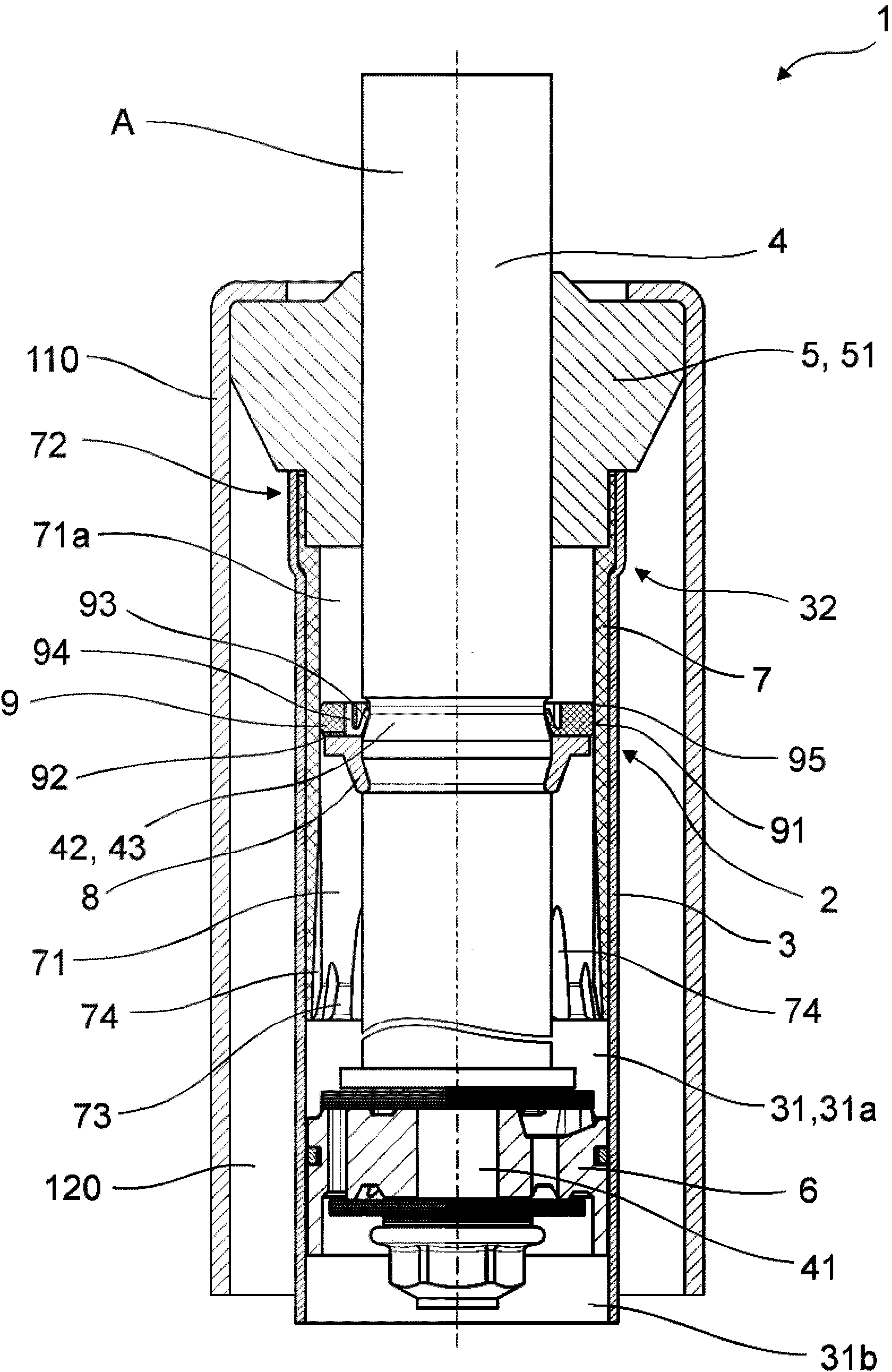
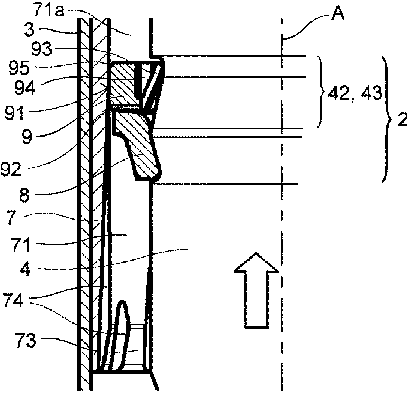
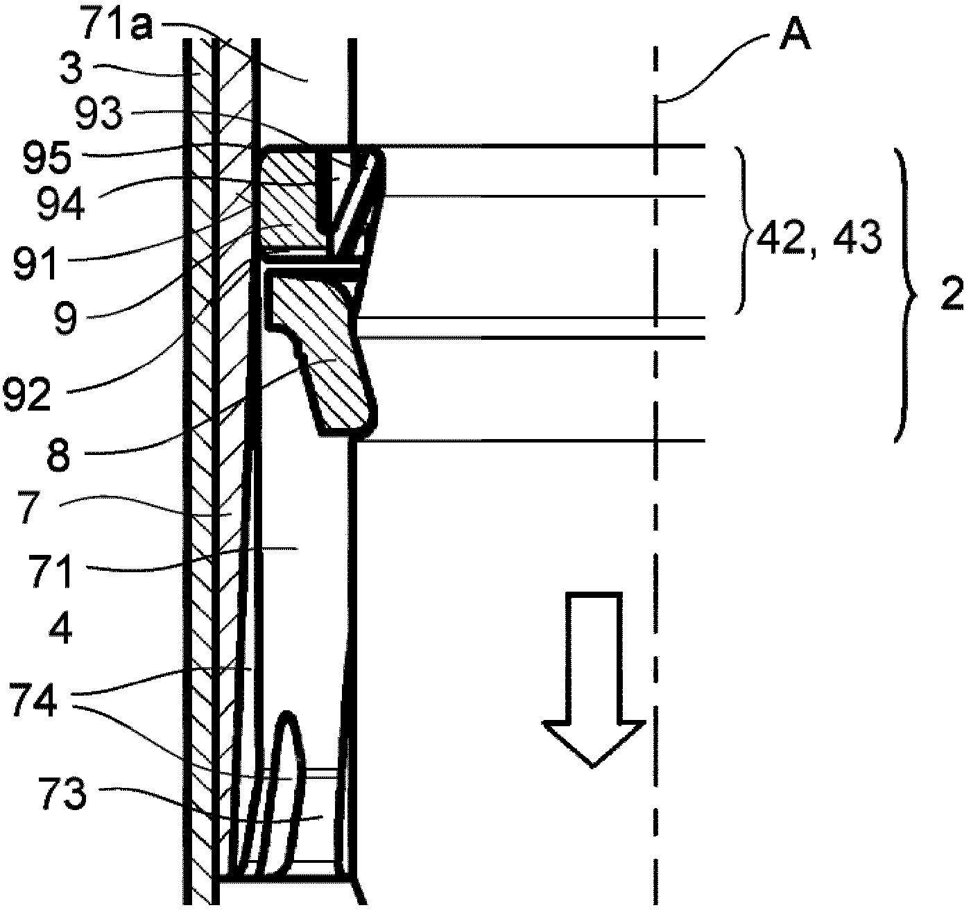
[0065] figure 1 and Figure 4 A variant embodiment of the shock absorber 1 according to the invention with a hydraulic end stop 2 is shown, the end stop 2 being designed as a tension stop. An embodiment as a pressure stop is not specifically shown in the drawings, but this is obviously equally possible.
[0066] exist figure 1The shock absorber 1 depicted in is a double-tube shock absorber and comprises a cylinder 3 surrounded by an outer tube 11 . The cylinder chamber 31 is completely filled with a liquid damping medium. Between the outer tube 11 and the cylinder 3 a compensation chamber 120 is radially delimited, which is filled with a defined quantity of damping medium. The remaining volume of the compensation chamber 120 is filled with gas. The cylinder chamber 31 and the compensating chamber 120 are connected via a bottom valve (not shown here), which restricts the damping medium flow between the two chambers. However, the use of the invention is not limited only to...
PUM
 Abstract
Description
Claims
Application Information
 - R&D
- Intellectual Property
- Life Sciences
- Materials
- Tech Scout
- Unparalleled Data Quality
- Higher Quality Content
- 60% Fewer Hallucinations
Browse by: Latest US Patents, China's latest patents, Technical Efficacy Thesaurus, Application Domain, Technology Topic, Popular Technical Reports.
© 2025 PatSnap. All rights reserved.Legal|Privacy policy|Modern Slavery Act Transparency Statement|Sitemap|About US| Contact US: help@patsnap.com