
Grinding device for head portion and two side faces of screwdriver cutter bar

A technology of leveling and tool bar, applied in the direction of grinding machine, manufacturing tool, grinding feed movement, etc., can solve the problems of increasing the working time of workers and lowering work efficiency, and achieves the effect of high work efficiency and burr removal.

Inactive Publication Date: 2014-07-02
宁波德诚工具有限公司
View PDF6 Cites 3 Cited by
  • Summary
  • Abstract
  • Description
  • Claims
  • Application Information

AI Technical Summary

Problems solved by technology

Most of the existing grinding devices are those with a single grinding wheel, which can only grind the surface of the product in one direction. At the same time, when grinding, the work efficiency of the grinding device of the single emery wheel becomes low, which increases the working hours of the workers.

Method used


Image

  • Grinding device for head portion and two side faces of screwdriver cutter bar
  • Grinding device for head portion and two side faces of screwdriver cutter bar
  • Grinding device for head portion and two side faces of screwdriver cutter bar

Examples


Embodiment 1

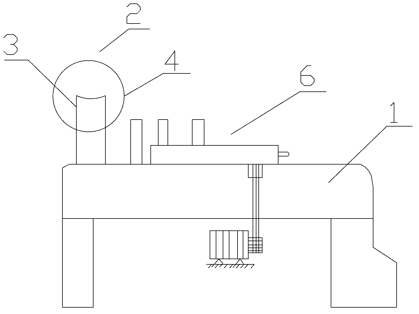
[0016] Example 1, such as figure 1 , figure 2 As shown, the grinding mechanism 2 includes a connecting rod 3 hinged on the support 1 and an electric grinding wheel 4 installed on the connecting rod. Corresponding to the manipulator 68, when it is necessary to process and polish the head of the knife bar, the manipulator 68 of the feeding mechanism clamps the knife bar, and drives the knife bar close to the working surface of the electric grinding wheel 4 through the first servo motor 64 and the second servo motor 66 Grinding the head of the shank.

Embodiment 2

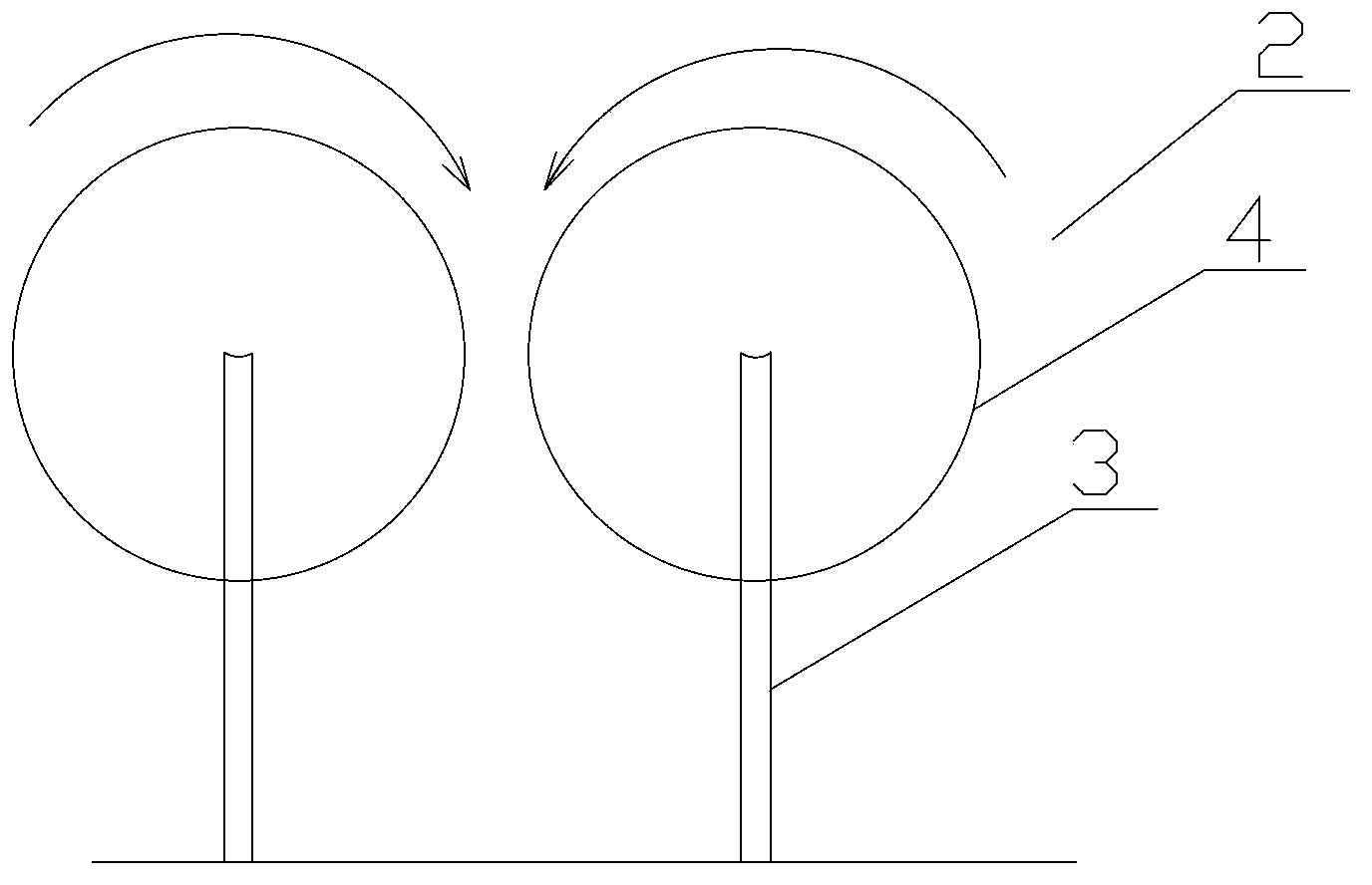
[0017] Example 2, such as image 3 As shown, the grinding mechanism 2 includes a connecting rod 3 hinged on the support 1 and an electric grinding wheel 4 mounted on the connecting rod. The number of the electric grinding wheels 4 is two, and the axes of the two electric grinding wheels 4 are parallel to each other. The working surfaces of the grinding wheels are opposite to each other with a gap left, and the direction of rotation is opposite. When it is necessary to process and polish both sides of the tool bar head, the tool bar is clamped by the manipulator 68 of the feeding mechanism 6, and passes through the first servo motor 64 and the second servo motor. Two servo motors 66 drive the knife bar close to the electric grinding wheel 4, and the knife bar is stretched into the gap between the two electric grinding wheels 4, and the two sides of the knife bar are polished by the electric grinding wheels 4 rotating in opposite directions.

[0018] The device adopts different ...


PUM


Abstract

A grinding device for the head portion and two side faces of a screwdriver cutter bar comprises a support, grinding mechanisms and a feeding mechanism, wherein the grinding mechanisms and the feeding mechanism are arranged on the support; the feeding mechanism corresponds to the grinding mechanisms. The grinding device for the head portion and the two side faces of the screwdriver cutter bar is provided with the different grinding mechanisms for the head portion and the two side faces of the screwdriver cutter bar, the corresponding grinding mechanisms are adjusted according to the needs of the different portions of the screwdriver cutter bar, burrs on the surface of the screwdriver cutter bar are removed effectively, and working efficiency is high.

Description

technical field [0001] The invention relates to a head and double-side grinding device, in particular to a screwdriver cutter bar head double-side grinding device. Background technique [0002] It is a metallographic equipment used for rough grinding on the surface of the cut sample or the surface of the unprocessed sample. It can improve the quality and work efficiency of sample preparation. The grinding of this machine generally adopts wet grinding, which can greatly reduce the dust flying pollution during grinding, and has the advantages of convenient operation, safety, reliability and easy maintenance. Most of the existing grinding devices are those with a single grinding wheel, which can only grind the surface of the product in one direction. At the same time, when grinding, the work efficiency of the grinding device of the single emery wheel becomes low, which increases the working hours of the workers. Contents of the invention [0003] The technical problem to be...

Claims


Application Information

Patent Timeline
IPC IPC(8): B24B9/04
CPCB24B9/00B24B41/005
Inventor 钱贤平
Owner 宁波德诚工具有限公司
Learn More