Eureka AIR delivers breakthrough ideas for toughest innovation challenges, trusted by R&D personnel around the world.

Main shaft self-locking mechanism

A spindle and self-locking technology, applied in the direction of portable motorized devices, manufacturing tools, etc., can solve the problems of high friction noise and small self-locking torque, and achieve the effect of large torque

Active Publication Date: 2014-07-02
POSITEC POWER TOOLS (SUZHOU) CO LTD
View PDF7 Cites 0 Cited by
  • Summary
  • Abstract
  • Description
  • Claims
  • Application Information

AI Technical Summary

Problems solved by technology

This mechanism usually has the following problems: (1) the self-locking torque is small; (2) the friction noise is large when braking

Method used


Image

  • Main shaft self-locking mechanism
  • Main shaft self-locking mechanism
  • Main shaft self-locking mechanism

Examples


Embodiment 1

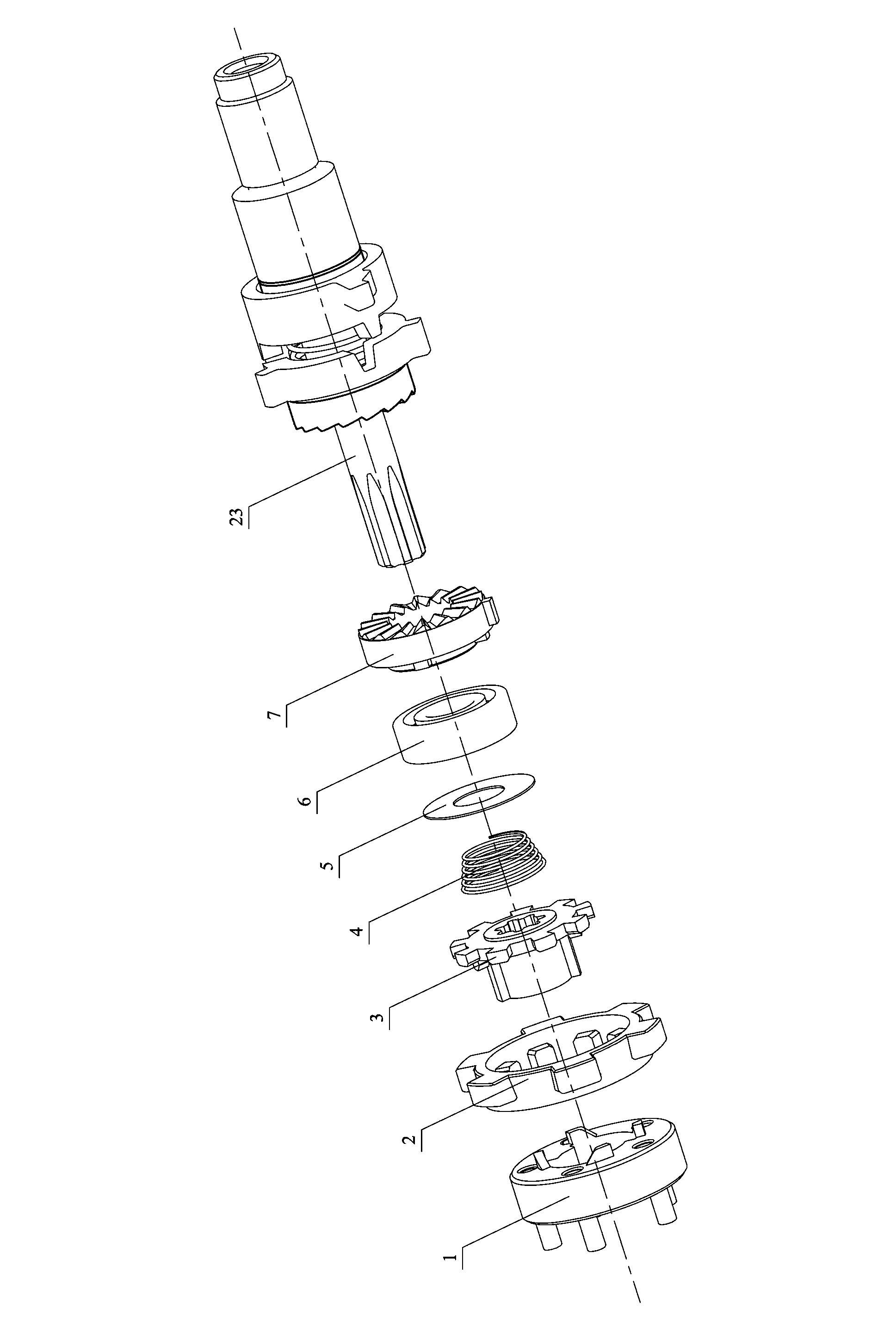
[0035] Embodiment one: see attached figure 1 to attach Figure 4 shown. A main shaft self-locking mechanism, which is connected with the main shaft 23 to realize the self-locking function for the main shaft 23 .

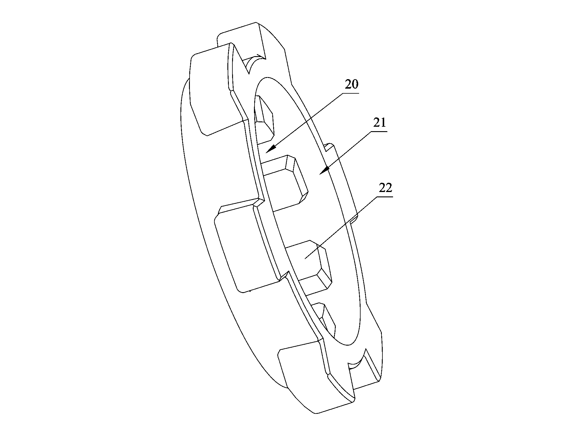
[0036] The spindle self-locking mechanism includes a planet carrier 1 , a fixed plate 2 , an adapter plate 3 , and a compression spring 4 .

[0037] The adapter plate 3 and the main shaft 23 are fixedly connected by splines and rotate coaxially. A gasket 5 is provided between the adapter plate 3 and the compression spring 4 , and the main shaft 23 is provided with a bearing 6 and a static end tooth 7 . It is defined that the main shaft 23, the static end teeth 7, and the bearing 6 together form the collet 8.

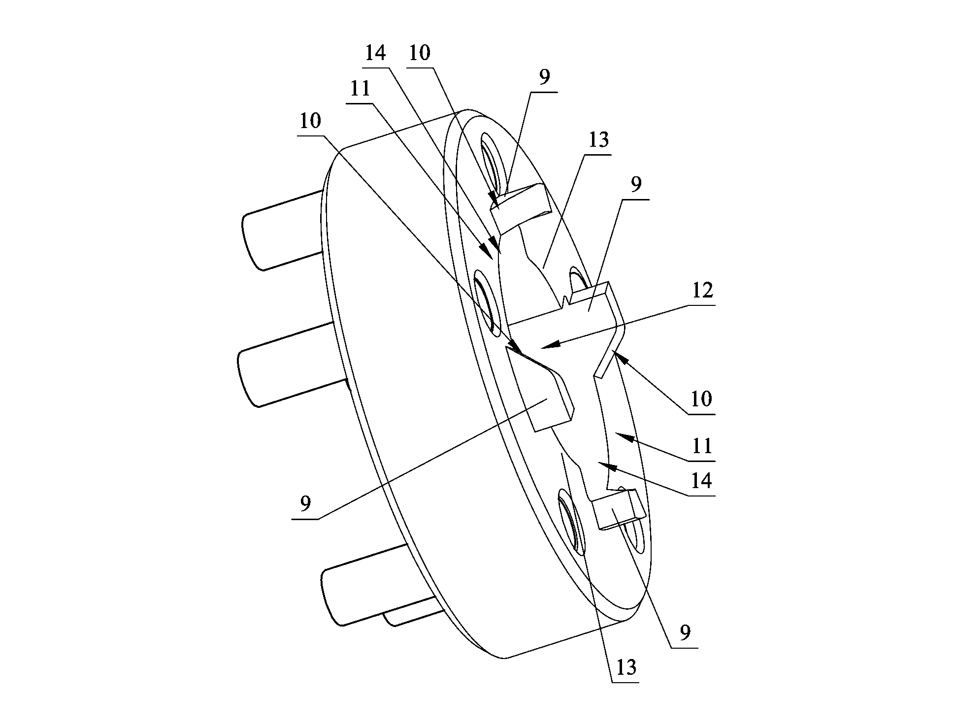
[0038] The planetary carrier 1 is coaxially connected with the adapter disc 3 . At least one pair of first bosses 9 are provided on the end surface of the planet carrier 1 near the adapter plate 3 . A pair of first bosses 9 are symmetrically arranged along...


PUM


Abstract

The invention relates to a main shaft self-locking mechanism which comprises a planet carrier, a fixed disc, a through connection disc and a compressed spring. The through connection disc is connected with a main shaft, a first boss is arranged on the end face of the planet carrier, the lateral face of the first boss is a first slope, and the first slope and the end face of the planet carrier form a sliding groove. Containing space is formed in the center of the planet carrier, the inner lateral wall of the containing space is provided with a protruding first locating block, and a circumferential locating groove is formed by the first locating block. The through connection disc comprises a connecting part and a locating part, the lateral wall of the connecting part is provided with a second locating block which is inserted into the containing space, the end face of the side, close to the planet carrier, of the locating part is provided with a second boss, the lateral face of the second boss is a second slope matched with the first slope, the locating part is a fluted disc, a tooth groove is formed in the fixed disc, and the locating part is arranged in the tooth groove. The compressed spring is connected with the through connection disc and stretches in the axial direction. By means of the main shaft self-locking mechanism, the through connection disc is meshed with or separated from the fixed disc to achieve the main shaft self-locking function, torque during self locking is large, and noise cannot be generated.

Description

technical field [0001] The invention relates to a mechanism for realizing the self-locking function of the main shaft, in particular to the main shaft self-locking mechanism used in electric tools such as electric drills and screwdrivers. Background technique [0002] In the prior art, the mechanism for realizing the self-locking function of the electric drill spindle is usually implemented by using rollers through friction. This mechanism usually has the following problems: (1) the self-locking torque is small; (2) the friction noise is relatively large during braking. Contents of the invention [0003] The purpose of the present invention is to provide a main shaft self-locking mechanism with large self-locking torque and no noise. [0004] In order to achieve the above object, the technical scheme adopted in the present invention is: [0005] A main shaft self-locking mechanism, which is connected with the main shaft to realize the self-locking function for the main s...

Claims


Application Information

Patent Timeline
IPC IPC(8): B25F5/00
Inventor 吴爱民
Owner POSITEC POWER TOOLS (SUZHOU) CO LTD
Why Eureka
Eureka Blog
Learn More