Novel throwing machine

A throwing machine, a new type of technology, applied in the direction of throwing machines, transportation and packaging, etc., can solve the problems of waste of manpower, loss of materials, waste of resources and costs, etc., to save manpower, good throwing effect, save resources and costs Effect

Active Publication Date: 2014-07-02
铜陵有色兴铜机电制造有限公司
View PDF8 Cites 2 Cited by
  • Summary
  • Abstract
  • Description
  • Claims
  • Application Information

AI Technical Summary

Problems solved by technology

[0002] In the field of metallurgical technology, the throwing machine, as a common pyrometallurgical mechanical equipment, has a wide range of applications. The existing throwing machines have complex and diverse structures, high cost, and poor throwing effects. A conveyor belt is set in the throwing bin, and the material is thrown into the furnace through high-speed rotation. However, in the prior art, a large part of the ma

Method used


Image

  • Novel throwing machine

Examples


Embodiment Construction

[0010] In order to make the objectives, technical solutions and advantages of the present invention clearer, the following further describes the present invention in detail with reference to the accompanying drawings and embodiments. It should be understood that the specific embodiments described herein are only used to explain the present invention, but not to limit the present invention.

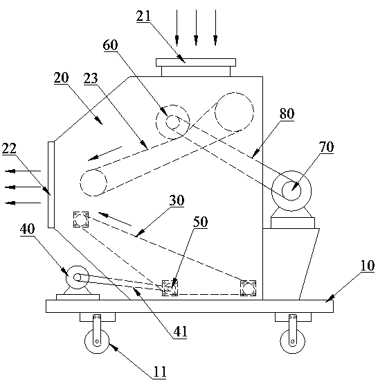
[0011] See figure 1 , figure 1 It is a schematic diagram of the structure of a novel thrower of the present invention.

[0012] The new type of throwing machine includes a frame plate 10 and a throwing bin 20. The throwing bin 20 is fixed on the frame plate 10, and a roller 11 is arranged below the frame plate 10 for easy dragging or rotation. In the entire throwing machine, the top of the throwing bin 20 is provided with a feed inlet 21, and the side is provided with a discharge port 22. The upper part of the inner cavity of the throwing bin 20 is provided with a conveyor belt 23. The sides...


PUM


Abstract

The invention relates to a novel throwing machine. The novel throwing machine comprises a machine frame board and a throwing bin which is fixed on the machine frame board, the top of the throwing bin is provided with a feeding port, the side face of the throwing bin is provided with a discharging port, a conveying belt is arranged on the upper portion in an inner cavity of the throwing bin, and two sides of the conveying belt are arranged at the feeding port end and the discharging port end of the throwing bin. The novel throwing machine further comprises a high-speed conveyor belt, a motor and a rotating roller, the high-speed conveyor belt is arranged on the lower portion in the inner cavity of the throwing bin, one side of the high-speed conveyor belt is arranged at the discharging port end, the other side of the high-speed conveyor belt is arranged on one side, away from the discharging port, of the bottom of the throwing bin, the motor is arranged on the part, outside the throwing bin, of the machine frame board, the rotating roller is arranged in the throwing bin and pressed on the inner surface of the high-speed conveyor belt, and the rotating roller is connected with the motor through a belt. By means of the novel throwing machine, scattered materials do not need to be cleared away manually, the throwing effect is good, resources and cost are saved, and manpower is saved.

Description

Technical field [0001] The invention relates to the technical field of pyrometallurgical machinery and equipment, in particular to a new type of thrower. Background technique [0002] In the field of metallurgical technology, as a common pyrometallurgical equipment, the thrower has a wide range of applications. The existing thrower has complex and diverse structures, high cost, and poor throwing effect. A conveyor belt is set in the throwing bin, and the material is thrown into the furnace through high-speed rotation. However, in the prior art, the conveying belt is used for throwing, and a large part of the material will be scattered to the bottom of the throwing bin and needs to be manually removed and collected Disposal to prevent too much material deposited inside, jam the conveyor belt, and then throw the collected materials into the furnace for use, which wastes a lot of manpower, and it will lose a lot of materials for a long time, wasting resources and costs. Summary of ...

Claims


Application Information

Patent Timeline
IPC IPC(8): B65G31/02
Inventor 施发达吴旭光王永辉
Owner 铜陵有色兴铜机电制造有限公司
Why Eureka
Try Eureka