Groove type sludge turning-throwing machine and installation method of turning-throwing drums thereof

A technology of turning drum and turning machine is applied in the directions of sewage/sludge fertilizer, organic fertilizer, fertilization device, etc., which can solve the problems of low turning efficiency, small turning ability and poor maintenance, so as to improve turning efficiency. , Avoid turning over dead corners, improve reliability and durability

Inactive Publication Date: 2017-05-31
CHONGQING HUAYU HEAVY IND ELECTROMECHANICAL CO LTD
View PDF5 Cites 1 Cited by
  • Summary
  • Abstract
  • Description
  • Claims
  • Application Information

AI Technical Summary

Problems solved by technology

The turning drum is one of the main components of the sludge turning machine. The existing turning drums have problems such as complex structure, low reliability, poor maintainability, low turning efficiency, small turning capacity, and high energy consumption.

Method used


Image

  • Groove type sludge turning-throwing machine and installation method of turning-throwing drums thereof
  • Groove type sludge turning-throwing machine and installation method of turning-throwing drums thereof
  • Groove type sludge turning-throwing machine and installation method of turning-throwing drums thereof

Examples


Embodiment Construction

[0038] The present invention will be described in detail below in conjunction with the accompanying drawings and specific embodiments.

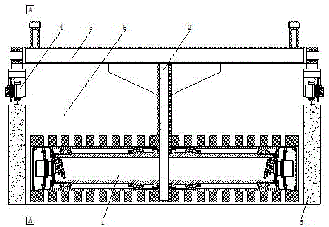
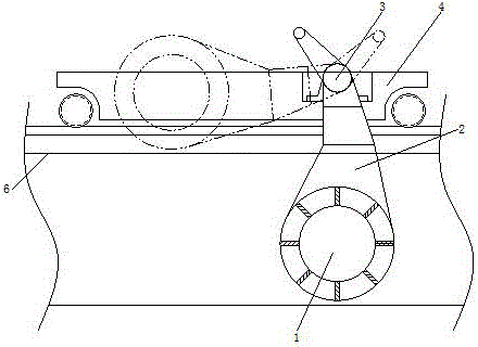
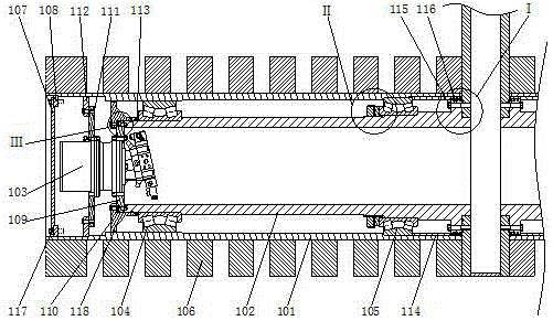
[0039] Such as Figure 1 to Figure 6 As shown, the present invention provides a trough sludge turning machine, comprising at least a frame 3, a walking mechanism 4, a turning arm 2 and two turning drums 1. The frame 3 consists of two The side walking mechanism 4 is supported, the upper part of the turning arm 2 is connected with the middle part of the frame 3, and the two sides of the lower part of the turning arm 2 are symmetrically connected with two turning and throwing drums 1; the turning and throwing drum 1 includes a rotating drum 101, a support cylinder 102 and a hydraulic drive device, the support cylinder 102 is arranged in the rotating drum 101 and its inner end is fixedly connected with the turning arm 2, and the first bearing 104 and the second bearing are connected between the inner wall of the rotating drum 101 and the supporti...


PUM


Abstract

The invention discloses a groove type sludge turning-throwing machine and an installation method of turning-throwing drums thereof. The groove type sludge turning-throwing machine comprises a machine body, wherein the machine body is at least formed by a machine frame, walking mechanisms, a turning-throwing arm and the two turning-throwing drums; the machine frame is supported by the walking mechanism at two sides; the upper part of the turning-throwing arm is connected with the middle part of the machine frame; two sides of the lower part of the turning-throwing arm are symmetrically connected with the two turning-throwing drums; each turning-throwing drum comprises a rotary drum, a support cylinder and a hydraulic driving device, each support cylinder is arranged in the corresponding rotary drum, the inner end of each support cylinder is fixedly connected with the turning-throwing arm, and a first bearing, a second bearing, a first bearing fixing device and a second bearing fixing device are connected between the inner wall of each rotary drum and the corresponding support cylinder; the power input end of each hydraulic driving device is connected with the corresponding support cylinder, and the power output end of each hydraulic driving device is connected with the corresponding rotary drum. The groove type sludge turning-throwing machine has the advantages that the structure is simplified, the reliability and turning-throwing efficiency of the drums of the turning-throwing machine are improved, the turning-throwing ability is enhanced, and the energy consumption is decreased.

Description

technical field [0001] The invention relates to the technical field of sludge organic fertilizer production, in particular to a trough sludge turning and throwing machine and an installation method of the turning and throwing drum. Background technique [0002] With the growth of urban population, the amount of urban sewage treatment has increased rapidly, and the amount of sludge generated from sewage treatment has also continued to increase. According to the survey, 80% of domestic sludge has not been effectively treated and disposed of. Therefore, sludge treatment and disposal has become the top priority of sewage treatment plants and urban environmental sanitation. [0003] Common methods of sludge treatment include composting, landfilling and incineration, etc. Composting is a better way to deal with sludge. The turning and throwing machine is one of the most important equipment in the composting process. It is responsible for turning, stirring, and moving the material...

Claims


Application Information

Patent Timeline
Patent Type & Authority Applications(China)
IPC IPC(8): C05F7/00
CPCC05F7/00Y02A40/20
Inventor 吴忠保王勇韦易
Owner CHONGQING HUAYU HEAVY IND ELECTROMECHANICAL CO LTD
Why Eureka
Try Eureka