Long-span ballastless track bridge beam end structure

A ballastless track and long-span technology, applied in bridges, bridge parts, bridge construction, etc., can solve problems such as large force on fasteners and inability to solve structural influences, and achieve the effects of high precision, simple structure, and convenient construction

Inactive Publication Date: 2014-07-02
CHINA RAILWAY SIYUAN SURVEY & DESIGN GRP
View PDF0 Cites 9 Cited by
  • Summary
  • Abstract
  • Description
  • Claims
  • Application Information

AI Technical Summary

Problems solved by technology

Therefore, on long-span ballastless track bridges, the beam end rail lifting device cannot solve the problems of the i

Method used


Image

  • Long-span ballastless track bridge beam end structure
  • Long-span ballastless track bridge beam end structure
  • Long-span ballastless track bridge beam end structure

Examples


Example Embodiment

[0017] The present invention will be further described in detail below in conjunction with the accompanying drawings and specific embodiments to facilitate a clear understanding of the present invention, but they do not limit the present invention.
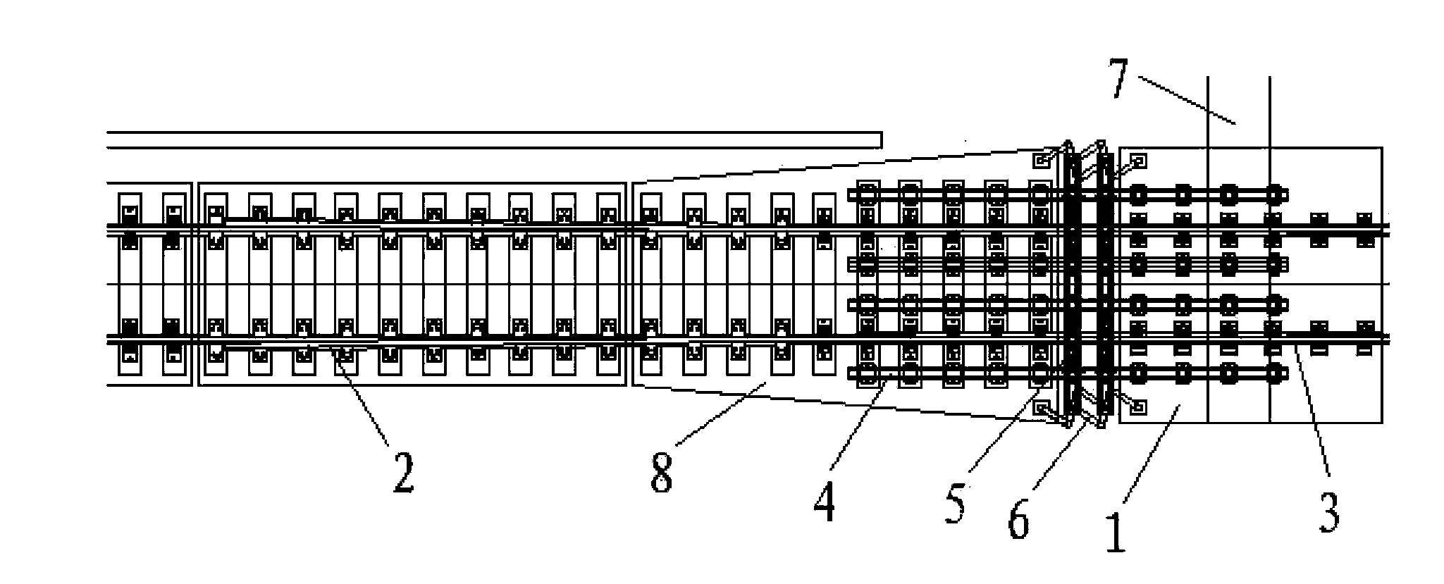
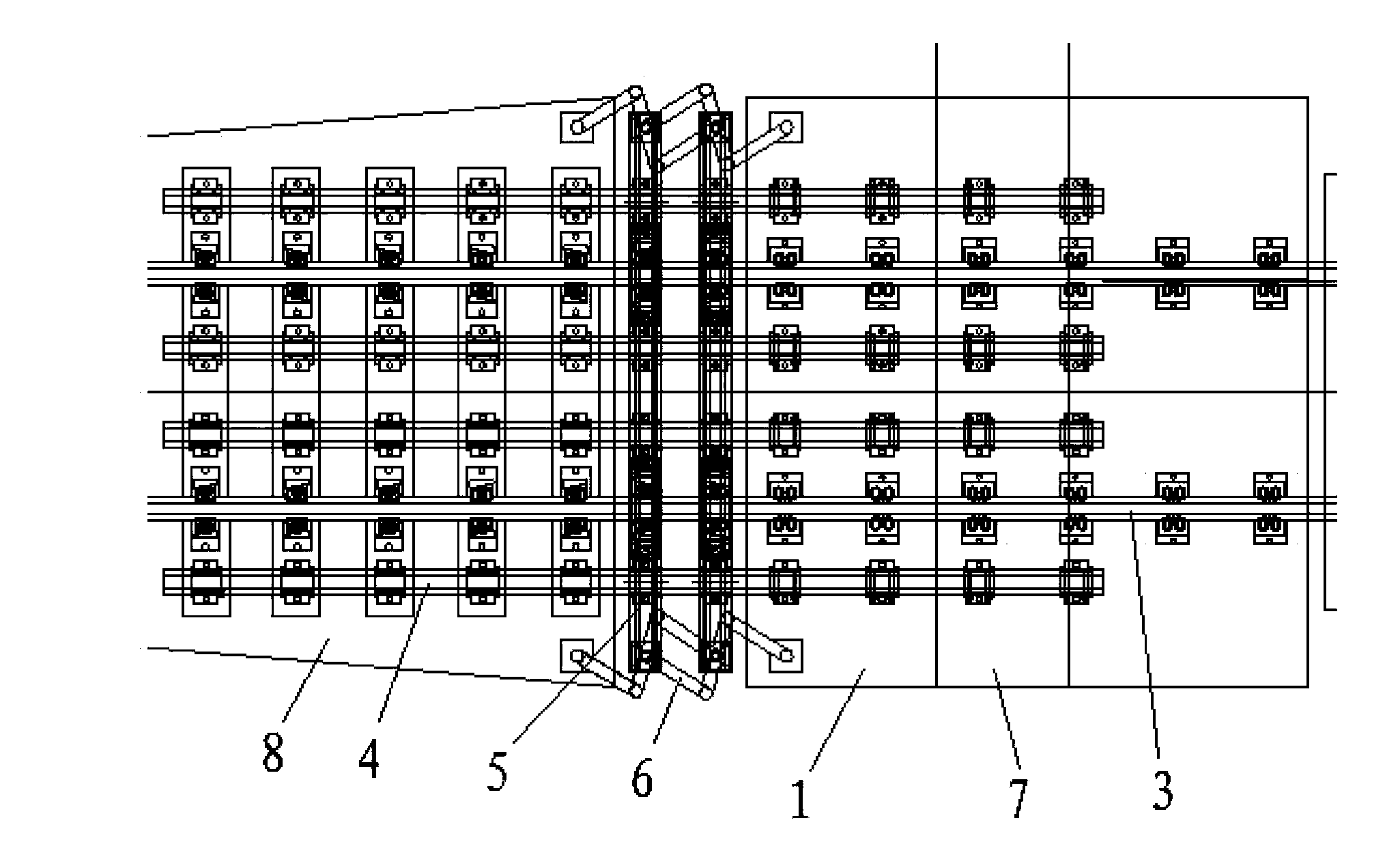
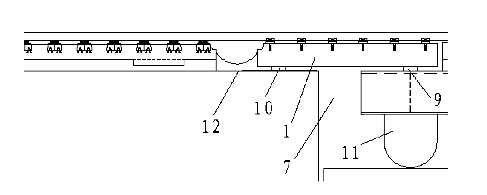
[0018] Such as Figure 1 to Figure 4 As shown, the present invention includes a transition plate 1, a telescopic adjuster 2, and a beam end lifting device. The transition plate 1 is located above the beam gap 7, and the lower surfaces of the two ends of the transition plate 1 are respectively connected to the ends of the long-span bridge and the upper surface of the simply supported beam ends through supports. The supports include two fixed supports 9 and two movable supports. Block 10. The two fixed bearings 9 are respectively located on the upper surface of the end of the long-span bridge at one end of the girder joint 7, and correspond to the steel bridge support 11 arranged between the end of the long-span bridge and the pier in...


PUM


Abstract

The invention relates to a railway track structure system, in particular to a long-span ballastless track bridge beam end structure which comprises a transition plate, a beam end track lifting device and a telescopic regulator. The transition plate is located above a beam joint, the lower surfaces of two ends of the transition plate are connected with the upper surfaces of ends of a beam body through supports, the transition plate and a roadbed slab on one side of the beam joint are connected through the track lifting device, and the telescopic regulator used for balancing track longitudinal stress is located on a long-span bridge beam end or a steel track of an adjacent simply-supported beam. The structure is simple in structure, convenient to install and capable of well adapting to large telescopic displacement of a long-span ballastless track concrete bridge beam end and a steel beam end, reduces influences of beam end corners on the ballastless track structure, achieves a track structure cross large beam joint structure and can guarantee stable running of a train.

Description

technical field [0001] The invention relates to a railway track structure system, in particular to a beam end structure of a long-span ballastless track bridge. Background technique [0002] Under the influence of train load, temperature, shrinkage and creep, etc., long-span bridges have large expansion and contraction displacements and beam end rotation angles. In order to reduce the impact of expansion and contraction displacement and beam end angle on the track structure, make the track structure span the girder gap, and ensure the smooth passage of trains, at present, large-span bridges at home and abroad mainly use transition plates at the beam end to reduce the impact of bridge angle on the track. The end rail lifting device is adapted to the telescopic displacement of the bridge beam end. But the above structure has the following problems: [0003] (1) Long-span concrete bridges and steel girders have large expansion and contraction displacements when the temperatur...

Claims


Application Information

Patent Timeline
IPC IPC(8): E01D19/12
Inventor 孙立王森荣张珍珍戴金松陈潇
Owner CHINA RAILWAY SIYUAN SURVEY & DESIGN GRP
Why Eureka
Try Eureka