Plate type phase-change thermal storage heat exchanger capable of supplying heat stably

A phase change heat storage and heat exchanger technology, applied in the direction of heat exchanger types, indirect heat exchangers, heat storage equipment, etc.

Inactive Publication Date: 2014-07-02
SICHUAN PROVINCIAL ARCHITECTURAL DESIGN & RES INST
View PDF9 Cites 19 Cited by
  • Summary
  • Abstract
  • Description
  • Claims
  • Application Information

AI Technical Summary

Problems solved by technology

[0003]The present invention overcomes the deficiencies of the prior art and provides a plate type phase change heat storage heat exchanger with stable heat supply, which solves the inconvenience of the previous heat exchange devices Disassembly, cannot be used for heat exchange with different heat exchange fluids and unstable heat supply

Method used


Image

  • Plate type phase-change thermal storage heat exchanger capable of supplying heat stably
  • Plate type phase-change thermal storage heat exchanger capable of supplying heat stably
  • Plate type phase-change thermal storage heat exchanger capable of supplying heat stably

Examples


Embodiment 1

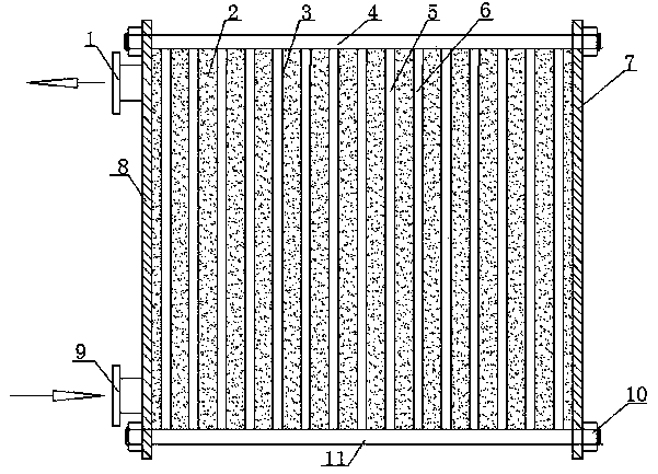
[0023] like figure 1 , Figure 4 The shown plate type phase change heat storage heat exchanger with stable heat supply includes a plurality of sealed boxes 3 arranged in parallel. The inside of the sealed box 3 is provided with a phase change heat storage body 2, and at the four corners of the sealed box 3 Corner holes 13 are arranged at each place, and a sealing member 16 is arranged between any two adjacent sealing boxes 3. The sealing member 16 isolates the two corner holes 13 on the same side of the sealing box 3, and any two adjacent Adjacent seals 17 form an included angle of 180° and are arranged in parallel, and the plurality of seal boxes 3 are surrounded by seals 17 to form spaced distribution of hot working medium flow chambers 5 and cold working medium flow chambers 6. The cavity thickness of the working medium flow chamber 5 and the cold working medium flow chamber 6 is 0 ~ 0.5 decimeters; it also includes an external frame, which compresses and seals the sealed...

Embodiment 2

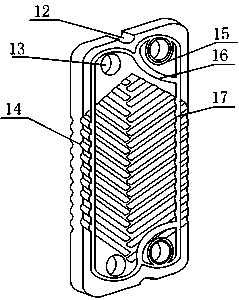
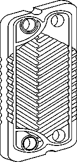
[0032] like figure 2 and image 3 As shown, on the basis of Embodiment 1, this embodiment adds an optimized seal, specifically: the same side end of the seal 17 is provided with an isolation seal 16, and the isolation seal 16 seals the same side of the box 3 The two corner holes 13 are isolated.

[0033] The sealing member 17 is arranged to match the structure of the sealing box 3, which can be circular, square or any other shape, and can be selected according to the specific usage; the sealing member 17 of this embodiment is of a square structure, and the four corner holes 13 are located at the 17, the two corner holes on the same side are isolated from the other two corner holes 13 by the isolation seal 16, so that the other two corner holes 13, the seal 16 and the isolation seal 16 form a flow cavity, and the isolated corner The hole 13 does not enter the flow chamber when the working fluid flows in, but directly enters the next adjacent flow chamber, so that the workin...

Embodiment 3

[0036] In this embodiment, the following structure is added on the basis of embodiment 1 or embodiment 2: both vertical sides of the sealed box 3 are provided with pulsator channels 14 .

[0037] The pulsator channel 14 of this embodiment brings two benefits: the first benefit is that the internal turbulence of the heat exchange working fluid can be accelerated, so that the working medium flows more comprehensively on the surface of the sealed box 3, and the working medium is not easy to scale; The second advantage is that the contact area between the working fluid and the phase-change heat storage body 2 is increased, thereby enhancing the heat transfer effect, making the heat storage and heat dissipation more rapid and uniform, and making the heat transfer more stable.


PUM


Abstract

The invention discloses a plate type phase-change thermal storage heat exchanger capable of supplying heat stably. The plate type phase-change thermal storage heat exchanger comprises a plurality of seal boxes arranged in parallel. A phase-change thermal storage body is arranged in each seal box. Corner holes are formed in the four corners of each seal box respectively. A sealing part is arranged between any two adjacent seal boxes, and the two corner holes in the same side end of each seal box are separated through the sealing part. Any two adjacent sealing parts are arranged in parallel at the 180-degree included angle. Hot working medium flowing cavities and cold working medium flowing cavities are defined by the seal boxes through the sealing parts, wherein the hot working medium flowing cavities and the cold working medium flowing cavities are distributed alternately. The plate type phase-change thermal storage heat exchanger further comprises an outer frame. The seal boxes are pressed tightly and sealed by the outer frame. A cold working medium inlet and outlet and a hot working medium inlet and outlet are further formed in the outer frame and are communicated with the corner holes. The plate type phase-change thermal storage heat exchanger is small in size and convenient to assemble, disassemble and maintain; phase-change thermal storage materials are adopted for thermal storage, so the defect that heat supply is not stable is effectively overcome, the heat supply time is prolonged, the stable heat supply temperature can be maintained, the stability is good, and the working media do not influence each other.

Description

technical field [0001] The invention relates to the field of heat storage and heat exchange, in particular to a plate type phase change heat storage heat exchanger with stable heat supply. Background technique [0002] In the heating system, due to the unstable energy of some heat sources such as solar energy, the heat supply is intermittent or stops for some time, which limits the application of this part of the heat source and leads to the waste of heat. Phase change heat storage materials have been used more and more in heating systems due to their large heat storage and stable temperature characteristics. Patent CN103062828A discloses a heat supply system for a closed flat plate phase-change heat storage tank. In this invention, a number of phase-change heat storage plates are arranged in the heat storage tank. The phase-change heat storage plate is fully contacted to store heat and release heat. It solves the problems of the existing heat storage tanks with complex str...

Claims


Application Information

Patent Timeline
Patent Type & Authority Applications(China)
IPC IPC(8): F28D9/02F28D20/00
CPCY02E60/142Y02E60/14
Inventor 赵娟侯文李纯章一萍
Owner SICHUAN PROVINCIAL ARCHITECTURAL DESIGN & RES INST
Why Eureka
Try Eureka