Unlock instant, AI-driven research and patent intelligence for your innovation.

A control switch for heat conduction

A technology for controlling switches and heat conduction, applied in heat exchange equipment, indirect heat exchangers, lighting and heating equipment, etc., can solve problems such as high valves and inability to achieve transfer effects, and achieve low production costs, simple structure, and reasonable settings Effect

Active Publication Date: 2016-04-20
TAICANG SANYI HEATING & CHILLING PROJECT CO LTD
View PDF6 Cites 0 Cited by
  • Summary
  • Abstract
  • Description
  • Claims
  • Application Information

AI Technical Summary

Problems solved by technology

[0003] However, the current problem is that the heat pipe is an uninterrupted process when transferring heat from the high temperature part to the low temperature part, and in the above occasions we only need to transfer the excess heat, or selectively accept the heat, that is, when the temperature When a certain temperature is reached, the heat transfer of the heat pipe is carried out
This kind of free choice will inevitably have higher requirements on the valve, and none of the existing valves can achieve this transmission effect

Method used


Image

  • A control switch for heat conduction
  • A control switch for heat conduction
  • A control switch for heat conduction

Examples


Embodiment Construction

[0021] The present invention will be further described below in conjunction with the accompanying drawings.

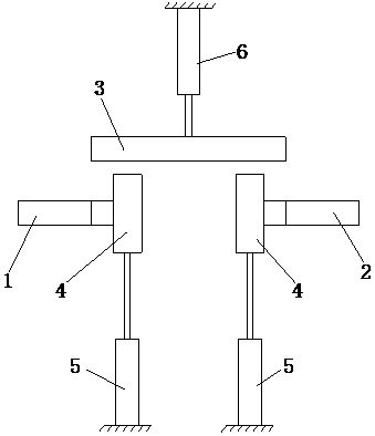
[0022] Such as Figure 1-6 As shown, a control switch for heat conduction according to the present invention includes a high-temperature heat pipe 1 and a low-temperature heat pipe 2, and a heat transfer pipe 3, two heat-insulation cotton boards 4, and two Cylinder one 5 and cylinder two 6, high-temperature heat pipe 1 and low-temperature heat pipe 2 are all provided with protruding end 1-1, and both ends of transfer heat pipe 3 are provided with concave end 3-1 matching with protruding end 1-1; The bottom end of the heat cotton plate 4 is fixedly connected with the telescopic rod of the cylinder one 5, and the middle part of the transfer heat pipe 3 is fixedly connected with the telescopic rod of the cylinder two 6; connected to the control device. The concrete connection mode of electric control device and cylinder one 5 and cylinder two 6 is prior art, and control...


PUM


Abstract

The invention relates to the technical field of heating industry, in particular to a heat transmission control switch. The heat transmission control switch comprises a high-temperature heat pipe and a low-temperature heat pipe, a transmission heat pipe, two heat insulation cotton plates, two first cylinders and a second cylinder are arranged between the high-temperature heat pipe and the low-temperature heat pipe, each of the high-temperature heat pipe and the low-temperature heat pipe is provided with a convex end, and two ends of the transmission heat pipe are provided with concave ends matched with the convex ends. The bottom ends of the heat insulation cotton plates are fixedly connected with telescopic rods of the first cylinders, and the middle of the transmission heat pipe is fixedly connected with a telescopic rod of the second cylinder. The heat transmission control switch further comprises an electric control device which is connected with the first cylinders and the second cylinder. In use of the heat transmission control switch, heat transmission time between the high-temperature heat pipe and the low-temperature heat pipe can be selected freely, defects of traditional switches are avoided, and great convenience is provided for a user. Moreover, the heat transmission control switch has the advantages of simple structure, reasonability in setup, low manufacturing cost and the like.

Description

technical field [0001] The invention relates to the technical field of heating industry, in particular to a control switch for heat conduction. Background technique [0002] A heat pipe is a device that transfers energy from an evaporator that absorbs heat to an evaporator that releases heat by evaporating and condensing a working fluid contained therein. Due to the high heat transfer efficiency and no noise of heat pipes, the application of heat pipes has become more and more popular, not only in some industrial production fields, but also in refrigeration and heating systems. [0003] However, the current problem is that the heat pipe is an uninterrupted process when transferring heat from the high temperature part to the low temperature part, and in the above occasions we only need to transfer the excess heat, or selectively accept the heat, that is, when the temperature When a certain temperature is reached, the heat transfer of the heat pipe is carried out. This free ...

Claims


Application Information

Patent Timeline
Patent Type & Authority Patents(China)
IPC IPC(8): F28F27/00F28D15/02
Inventor 顾蓉
Owner TAICANG SANYI HEATING & CHILLING PROJECT CO LTD