Ultrasonic flaw detection defect location method and ultrasonic flaw detector

A positioning method and ultrasonic technology, applied in the analysis of solids using sonic/ultrasonic/infrasonic waves, can solve the problems of time-consuming, relying on the subjective judgment of operators, poor reliability, etc., and achieve the effect of reducing workload

Active Publication Date: 2014-07-02
SENSE ENG SERVICES
View PDF5 Cites 15 Cited by
  • Summary
  • Abstract
  • Description
  • Claims
  • Application Information

AI Technical Summary

Problems solved by technology

) However, this judgment generally requires the inspector to carry out multiple inspection operations, combined with experience, it takes a long time and depends on the subjective judgment of the operator, and the reliability is poor

Method used


Image

  • Ultrasonic flaw detection defect location method and ultrasonic flaw detector
  • Ultrasonic flaw detection defect location method and ultrasonic flaw detector
  • Ultrasonic flaw detection defect location method and ultrasonic flaw detector

Examples


Embodiment Construction

[0056] In order to make the technical problems solved by the present invention, the technical solutions adopted and the technical effects achieved more clear, the technical solutions of the embodiments of the present invention will be described in further detail below in conjunction with the accompanying drawings. Obviously, the described embodiments are only the present invention. Some embodiments, not all embodiments. Based on the embodiments of the present invention, all other embodiments obtained by those skilled in the art without creative work shall fall within the protection scope of the present invention.

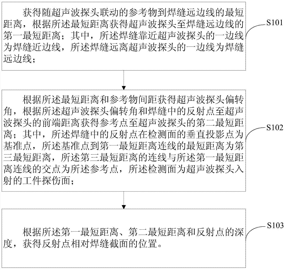
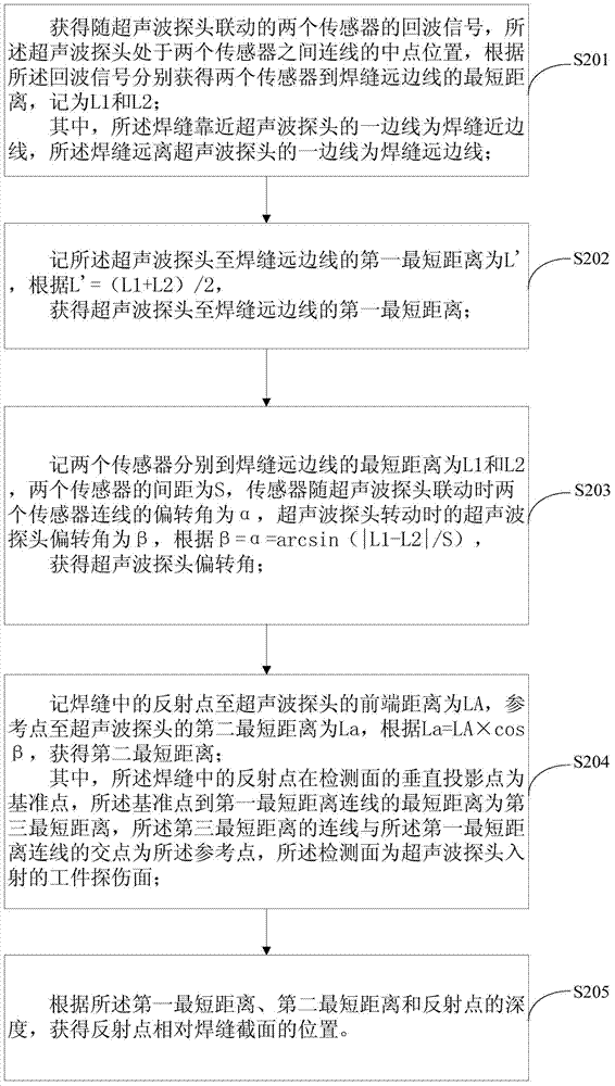
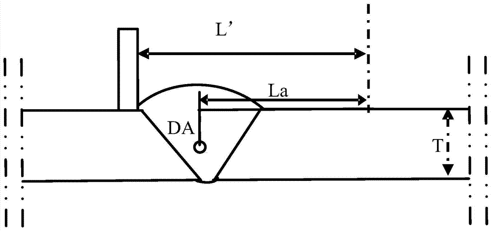
[0057] Please refer to figure 1 , Which is the method flowchart of the first embodiment of the ultrasonic flaw detection defect location method provided by the present invention. The ultrasonic flaw detection defect positioning method provided by the embodiment of the present invention can be applied to flat workpieces, vertical T-shaped workpieces, oblique T-shaped wo...


PUM


Abstract

The invention relates to the technical field of ultrasonic flaw detection, and in particular relates to an ultrasonic flaw detection defect location method and an ultrasonic flaw detector. The ultrasonic flaw detector comprises an echo detection circuit, wherein the echo detection circuit is connected to an ultrasonic probe; the ultrasonic probe is fixedly connected to a support; the support is provided with a reference substance linking along with the ultrasonic probe. The first shortest distance from the ultrasonic probe to a welding seam remote side line is obtained by utilizing the reference substance, and positional information of a reflection point relative to a welding seam cross section, namely the position of a flaw relative to the welding seam cross section, can be directly obtained by contrasting the first shortest distance from the ultrasonic probe to the welding seam remote side line with a second shortest distance from the ultrasonic probe to the reference substance and then matching with the depth of the reflection point, so that the detection workload of site flaw detection is reduced, the dependence on subjective judgment of operators is reduced, and the error rates of flaw position misjudgment and characteristic misjudgment are reduced.

Description

Technical field [0001] The invention relates to the technical field of ultrasonic flaw detection, in particular to an ultrasonic flaw detection defect positioning method and an ultrasonic flaw detector. Background technique [0002] At present, the welding seam detection of metal workpieces mostly adopts ultrasonic flaw detection method. Ultrasonic flaw detection is a method that uses ultrasonic energy to penetrate deep into the metal workpiece, and when one medium enters another medium, it can reflect on the interface to find defects. When the ultrasonic beam emitted by the probe meets inside the metal workpiece When a defect is reached, a reflected wave will be generated and a pulse waveform is formed on the phosphor screen. According to the position, height and dynamic form of these pulse waveforms, the position and equivalent of the defect can be judged and its nature can be further estimated. (Defect equivalent means that the return sound pressure of different types and siz...

Claims


Application Information

Patent Timeline
Patent Type & Authority Applications(China)
IPC IPC(8): G01N29/04
Inventor 汪月银
Owner SENSE ENG SERVICES
Why Eureka
Try Eureka