
Printing machine remote fault monitoring system and method

A printing machine and fault detection technology, applied in the direction of electrical program control, comprehensive factory control, comprehensive factory control, etc., can solve the problems that the printing machine system has not been widely used and the degree of network is not high

Inactive Publication Date: 2014-07-02
SHANGHAI UNIV
View PDF5 Cites 14 Cited by
  • Summary
  • Abstract
  • Description
  • Claims
  • Application Information

AI Technical Summary

Problems solved by technology

[0005] At present, the degree of networking in the domestic printing industry is not high, and most of them still use manual experience for fault diagnosis. Some researches on fault diagnosis based on artificial intelligence algorithms are mostly in the theoretical stage, and have not been widely used in actual printing machine systems.

Method used


Image

  • Printing machine remote fault monitoring system and method
  • Printing machine remote fault monitoring system and method
  • Printing machine remote fault monitoring system and method

Examples


Embodiment 1

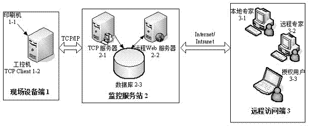
[0027] participate figure 1 , The remote fault diagnosis and monitoring system of this printing press includes a field device terminal 1, a monitoring service station 2 and a remote access terminal 3. The field device 1 communicates with the monitoring service station 2 via Ethernet, and the monitoring service station 2 communicates with the remote via the Internet or Intranet. Access terminal 3 communicates. Field device terminal 1 includes printing machine 1-1 and industrial computer 1-2. Monitoring service station 2 includes TCP server 2-1, remote Web server 2-2 and database 2-3. Remote access terminal 3 includes Authorized users 3-3, local experts 3-1 and remote experts 3-2 browsers, among them, the industrial computer on the field device side 1 collects real-time data from the printer on the field device side 1 through Ethernet, and the industrial computer 1-2 acts as The TCP client sends real-time data to the TCP server 2-1 of the remote monitoring service station 2, and t...

Embodiment 2

[0034] The remote fault detection method of the printing press adopts the above-mentioned system for remote diagnosis, including the following steps:

[0035] Step 1: The industrial computer 1-2 collects real-time data from the printing machine 1-1 and performs configuration;

[0036] Step 2: The industrial computer 1-2 serves as a TCP client to send the real-time data to the TCP server 2-1 of the remote monitoring service station 2;

[0037] Step 3: The database 2-3 classifies and stores the real-time data, manages users, monitors equipment, and performs remote fault diagnosis on equipment;

[0038] Step 4: The remote access terminal 3 accesses the remote Web server 2-2 through the Internet / Intranet to perform remote login, browse and query operations.

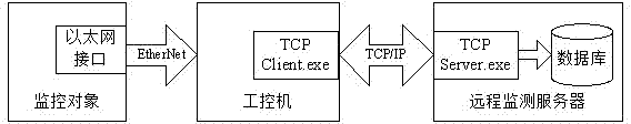
[0039] Such as figure 2 Shown is the block diagram of the basic process design for real-time data transmission on site. The industrial computer communicates with the equipment through Ethernet at the production site, can receive the ...


PUM


Abstract

The invention discloses a printing machine remote fault monitoring system and method. The system comprises a field equipment end, a monitoring service station and a remote access end. The field equipment end comprises a printing machine and an industrial personal computer, wherein the printing machine and the industrial personal computer are in a printing workshop, and the industrial personal computer collects real-time data from the printing machine through the Ethernet. The monitoring service station comprises a TCP server, a remote Web server and a database. The remote access end comprises an authorized user and a local and remote expert browser end. The industrial personal computer serves as a TCP client end and sends the real-time data to a TCP server module of the remote monitoring service station, and the remote Web server communicates with the remote access end through the Internet / Intranet. According to the system and method, field data are collected through a TCP / IP, a monitoring interface is published through a network, and remote login, real-time monitoring and fault analysis of users or expert browsers are achieved.

Description

Technical field [0001] The invention relates to the field of remote fault detection, in particular to a printing press remote fault monitoring system and method. Background technique [0002] With the continuous improvement of people’s living standards in our country, the demand for newspapers and advertisements has also increased. This puts forward higher requirements on the rotary press of printing presses, such as high-speed and high-quality printed matter, quick preparation, short-term start-up, Reduce the scrap rate, etc. To find the hidden troubles of the printing press early and repair it early, it is required that the fault information can be obtained by the operator or engineer in time. For those complex faults that on-site operators cannot solve, or fault predictions that can only be obtained through professional data analysis, it is necessary to seek help from experts and engineers in different places. However, it will be very difficult to implement this link interact...

Claims


Application Information

Patent Timeline
Patent Type & Authority Applications(China)
IPC IPC(8): G05B19/418
CPCY02P90/02
Inventor 邓丽王爱萍费敏锐王海宽
Owner SHANGHAI UNIV
Learn More