Chip type protecting element and batch manufacturing method thereof

A protection component and chip-type technology, which is applied in fuse manufacturing, electrical components, emergency protection devices, etc., can solve the problems of easy deposition of insulating shells by metal vapor, complex structural design of fuses, and difficulty in mass production, and achieve high reliability. The effect of performance and fusing consistency, improving high-voltage breaking capacity, and easy mass production

Active Publication Date: 2014-07-02
NANJING SART SCI & TECH DEV
View PDF9 Cites 1 Cited by
  • Summary
  • Abstract
  • Description
  • Claims
  • Application Information

AI Technical Summary

Problems solved by technology

Both of these two traditional protective element structures have two similar inherent defects: their end electrodes form a facing electrode structure, which is easy to form a continuous arc when breaking under high voltage; after the fuse is broken, its metal vapor It is easy to deposit on the surface of the insulating shell or substrate, resulting in a decrease in the insulation resistance of the product after breaking, and in serious cases, it may not be disconnected for a long time
This kind of fuse structure design reduces the impact of the end facing the electrode, and also forms the structural design of the floating fuse, which has a relatively large improvement in the breaking capacity and reliability of the surface mount fuse, but the fuse's The structural design is complex, the requirements for assembly equipment are high, the cost is high, and it is difficult to achieve mass production

Method used


Image

  • Chip type protecting element and batch manufacturing method thereof
  • Chip type protecting element and batch manufacturing method thereof
  • Chip type protecting element and batch manufacturing method thereof

Examples


Embodiment 1

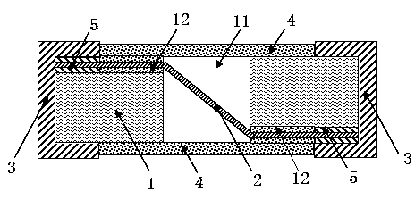
[0041] like figure 1 , figure 2 , image 3 As shown, the present invention provides a surface-mounted chip-type protection element, including an insulating substrate 1, a metal melt 2 disposed in the insulating substrate 1, end electrodes 3 formed at both ends of the insulating substrate 1 and formed on the insulating substrate 1. The protective layer 4 on the outer surface of the substrate 1, the metal melt 2 is electrically connected to the end electrodes 3 at both ends of the insulating substrate 1; a through hole 11 is formed in the middle of the insulating substrate 1, and the opening direction of the through hole 11 is in line with the end portion The electrodes 3 are vertical (that is, the connection line formed between the end electrodes is perpendicular to the axial direction of the through hole 11), and the upper and lower surfaces of the insulating substrate 1 (where upper and lower refer to figure 1 The direction in the middle) are respectively provided with gro...

Embodiment 2

[0065] As an improvement of Embodiment 1, such as figure 2 As shown, the through hole 11 is filled with an arc extinguishing material 111, which can extinguish the arc generated when the metal melt is broken, and improves the arc extinguishing capability of the product. The remaining structural features in this example are the same as those in Embodiment 1.

[0066] When mass-manufacturing the chip-type protective components provided in this example, the following steps are added between the mass-manufacturing step (3) conductive adhesive printing and step (4) protective layer addition in Example 1: arc-extinguishing material injection step:

[0067] The arc extinguishing material 111 is injected into the through hole 11 by using a dispensing machine dispensing process (other conventional processes can also be used), and the arc extinguishing material 111 can extinguish the arc generated at the moment when the metal melt 2 is disconnected , Adsorb metal vapor, reduce th...

Embodiment 3

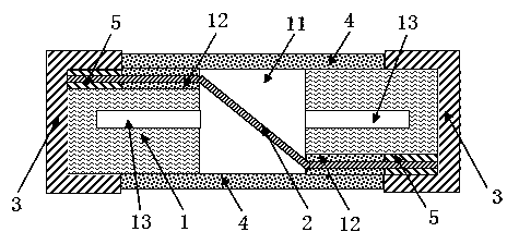
[0070] As an improvement of embodiment one or embodiment two, such as image 3 As shown, at least one decompression groove 13 is formed inside the insulating substrate 1, and the decompression groove 13 communicates with the through hole 11, so that the impact of the metal vapor pressure generated during breaking on the protective layer 4 can be reduced, and the durability of the product is improved. breaking capacity. The decompression groove 13 is preferably perpendicular to the direction of the through hole, and has a strong decompression capability. The rest of the structural features of the fuse in this example are the same as in the first embodiment or the same as in the second embodiment. The arc extinguishing material 111 can extinguish the arc generated when the metal melt is broken, and the decompression groove 13 can effectively reduce the pressure impact of the metal vapor, thereby obtaining a chip-type protective element with higher breaking capacity.

[0071] W...


PUM


Abstract

The invention discloses a chip type protecting element and a batch manufacturing method thereof. The element comprises an insulation base plate, a metal melt body, end electrodes and a protecting layer. A through hole is formed in the middle of the insulation base plate, and the opening direction of the through hole is perpendicular to the end electrodes. Grooves connected with the through hole are formed in the upper surface and the lower surface of the insulation base plate. The metal melt body penetrates in from a groove in one side of the insulation base plate, penetrates through the through hole in the opposite-angle direction and then penetrates out from a groove in the other side. The two ends of the metal melt body are fixed in the grooves through conducting resin and form electric connecting with the end electrodes at the two ends of the insulation base plate. The protecting layer is formed between the end electrodes. The design that the metal melt body forms a suspension melt wire structure by vertical opposite angle wire penetrating is used, the produced chip type protecting element has the advantages of being high in breaking capacity and high in reliability, two inherent defects of a traditional fuse structure are removed, structure design is simple, cost is low, and batch production can be achieved easily.

Description

technical field [0001] The invention belongs to the technical field of electrical components, and relates to a chip-type protection component, in particular to a high breaking capacity and high reliability overcurrent protection component with a vertical diagonal wire threading structure and a method for manufacturing the protection component. Background technique [0002] The protection element is generally connected in series in the circuit. When an abnormal phenomenon such as overcurrent or overheating occurs in the circuit, it will immediately cut off the circuit and play a protective role to prevent further expansion of the fault. Traditional protective components mainly have two structural forms, one is to install the fuse body horizontally through the wire and hang it in the tubular insulating shell, and use the end cap to seal the two ends of the tube body and provide the function of electrical connection with the internal fuse and surface welding The other is to...

Claims


Application Information

Patent Timeline
Patent Type & Authority Applications(China)
IPC IPC(8): H01H85/041H01H69/02
Inventor 南式荣刘明龙
Owner NANJING SART SCI & TECH DEV
Why Eureka
Try Eureka