Barrel-shaped mechanism with self-power-generation function

A technology of flashlights and DC generators, applied in the direction of engines, machines/engines, electrical components, etc., can solve the problems of insufficient power supply, poor light transmission, etc., and achieve the effects of easy disassembly, long life and good sealing

Active Publication Date: 2014-07-02
SHANGHAI UNIV
View PDF5 Cites 0 Cited by
  • Summary
  • Abstract
  • Description
  • Claims
  • Application Information

AI Technical Summary

Problems solved by technology

[0005] The research on passive spherical robots is deepening step by step. Most of these spherical robots are soft spherical shell structures. The communication, control and sensing equipment on the robot need to be installed on the internal cylindrical mechanism. In polar expeditions or Mars exploration, it is necessary to reach the robot Long battery life is required, and manual charging is impossible to ensure battery life. However, the cylindrical mechanism is inside the spherical robot, and the light transmission of the spherical shell is poor, which is prone to insufficient power supply.

Method used


Image

  • Barrel-shaped mechanism with self-power-generation function
  • Barrel-shaped mechanism with self-power-generation function
  • Barrel-shaped mechanism with self-power-generation function

Examples


Embodiment 1

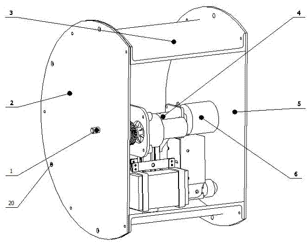
[0024] refer to Figure 1 ~ Figure 3 , the self-generating cylindrical mechanism, including a cylindrical shell (3), a left cover (2), a right cover (5), a shaft (1), a pendulum type autonomous generating mechanism (4) and a through-hole conductive slip ring (6). There are carabiner holes (20) on the flange side of the cylindrical housing (3), and the cylindrical mechanism can be installed in the internal hollow robot through carabiners (not shown in the figure). The pendulous self-generating mechanism (4) is coaxially installed in the cylindrical housing (3), and the pendulum-type self-generating mechanism (4) can rotate around the shaft (1), and through the large and small spur gears (18, 17) are meshed and driven to drive the rotor of the DC generator (12) to rotate relative to its stator to realize autonomous power supply. The through-hole conductive slip ring (6) can complete the connection between internal and external signal lines, ensuring good sealing of the ...

Embodiment 2

[0026] This embodiment is basically the same as Embodiment 1, and the special features are as follows:

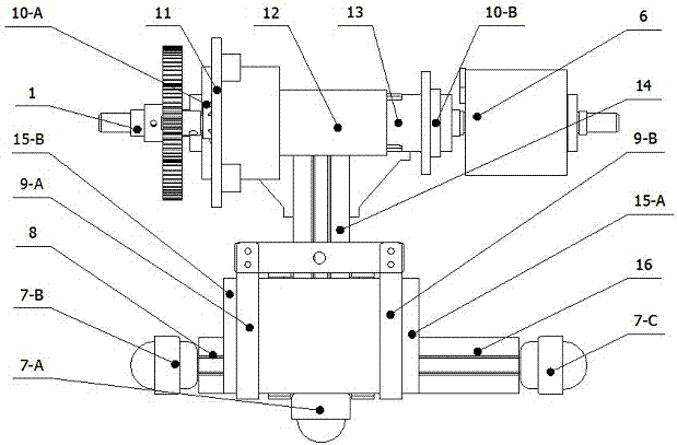
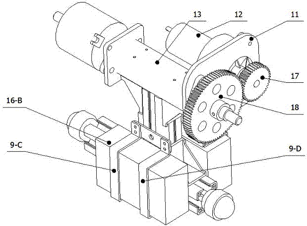
[0027] The pendulous self-generating mechanism (4) consists of a cross bar (13), a swing bar (14), a left bar (8), a right bar (16), a connecting plate (11), A large spur gear (18), a small spur gear (17), a DC generator (12), two bearing housings (10-A, 10-B), two low-temperature batteries (15-A, 15-B ) and four battery clamps (9-A, 9-B, 9-C, 9-D); one side of the connecting plate (11) is fixed on the cross bar (13) by countersunk screws, Fix the DC generator (12) stator on the other side with screws; the bearing seats (10-B, 10-A) are respectively fixed on the cross bar (13) and the connecting plate (11); the large The spur gear (18) is fixed on the shaft (1), and the small spur gear (17) is connected with the rotor of the DC generator (12); The left rod (8) and the right rod (16) are fixedly connected with the swing rod (14) by corner pieces; the battery clips (9-A...


PUM


Abstract

The invention discloses a barrel-shaped mechanism with a self-power-generation function. The barrel-shaped mechanism comprises a barrel-shaped shell, a left cover plate, a right cover plate, a shaft, a pendulous self-power-generation mechanism and a via-hole-type conducting sliding ring. The barrel-shaped mechanism can be installed in a hollow robot through a mountain climbing buckle by the barrel-shaped shell. The pendulous self-power-generation mechanism is coaxially installed in the barrel-shaped shell and can rotate around the shaft. Meshing transmission between a large straight gear and a small straight gear drives a rotor of a direct-current generator to rotate relative to a stator of the direct-current generator to achieve self-power-generation. An inner signal line can be connected with an outer signal line through the via-hole conducting sliding ring to guarantee good airtightness of the barrel-shaped mechanism. The barrel-shaped mechanism has the self-power-generation function, can achieve long-time endurance of the robot and is easy to disassemble or assemble and good in sealing performance.

Description

technical field [0001] The invention relates to a cylindrical mechanism, in particular to an autonomous power generating cylindrical mechanism. Background technique [0002] The cylindrical mechanism is rarely used in the field of robotics. It is mainly used in the field of passive data acquisition robots, and is mostly used as a supporting platform for robot controllers and sensors. [0003] After consulting the existing domestic and foreign literature, it is found that most of the cylindrical mechanisms of the existing passive data acquisition robots are fully enclosed, and the cylindrical mechanisms are mainly used to support the controller and sensors for data acquisition. It is necessary to ensure that all communication, control and sensing The device is powered well. Existing solutions include built-in battery with manual disassembly charging and built-in battery with solar panel charging. For the built-in battery with manual disassembly and charging scheme, du...

Claims


Application Information

Patent Timeline
Patent Type & Authority Applications(China)
IPC IPC(8): H02K7/18H02K7/116F03G3/06
Inventor 谢少荣冯凯姚骏峰邹旭东祝川
Owner SHANGHAI UNIV
Why Eureka
Try Eureka