
A ship propulsion system

A propulsion system and ship technology, applied in ship propulsion, propulsion components, propulsion device engines, etc., can solve the problems of many power conversion links, high noise, high energy consumption, etc., to improve stealth, reduce noise, and simplify the system process Effect

Active Publication Date: 2020-09-01
TECHNICAL INST OF PHYSICS & CHEMISTRY - CHINESE ACAD OF SCI
View PDF8 Cites 0 Cited by
  • Summary
  • Abstract
  • Description
  • Claims
  • Application Information

AI Technical Summary

Problems solved by technology

[0004] The technical problem to be solved by the present invention is to solve the problems of many power conversion links in the existing ship propulsion system, high noise, high energy consumption and low efficiency

Method used


Image

  • A ship propulsion system
  • A ship propulsion system
  • A ship propulsion system

Examples


Embodiment 1

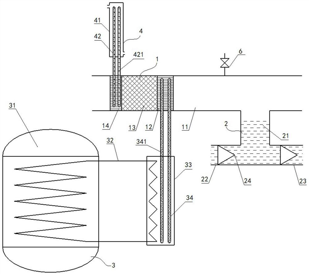
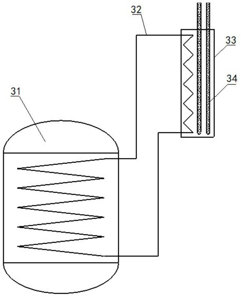
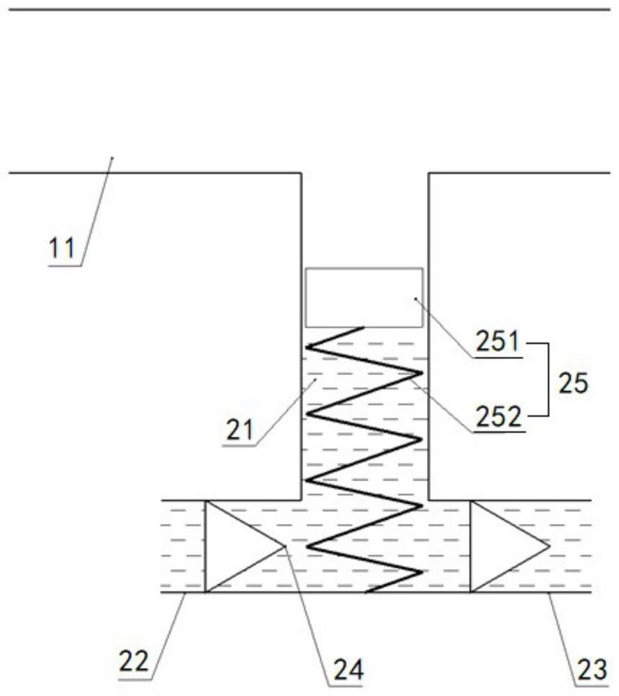
[0030] Such as figure 1 As shown, the ship propulsion system provided by the embodiment of the present invention includes a thermoacoustic engine 1, a propulsion device 2, a heating device 3 and a cooling device 4. The thermoacoustic engine 1 includes an acoustic tube 11 and sequentially connected in the acoustic tube 11. Heater 12, regenerator 13 and heat exchanger 14, heating device 3 is connected with heater 12, cooling device 4 is connected with heat exchanger 14, propulsion device 2 comprises branch pipe 21, and branch pipe 21 comprises the horizontal pipe that communicates with each other and vertical pipe. Straight pipe, the vertical pipe is vertically connected with the acoustic pipe 11, the water surface in the branch pipe 21 is located in the vertical pipe, one end of the horizontal pipe is the water inlet 22, and the other end of the horizontal pipe of the branch pipe 21 is the water outlet 23, and the water inlet 22 faces the ship. At the bow, the water outlet 23 i...

Embodiment 2

[0044] Such as Figure 4 As shown, this embodiment is basically the same as the first embodiment above, except that the first heat conducting element 34 in this embodiment is the second heat exchange circuit 342 , and the pump body 5 is arranged on the second heat exchange circuit 342 . Wherein, the second heat conducting member 42 is a third heat exchange circuit 422 , and the pump body 5 is arranged on the third heat exchange circuit 422 . The second heat exchange circuit between the heat exchanger and the heater can be driven by the pump body, and the third heat exchange circuit between the heat exchanger and the cooler can also be driven by the pump body, especially when the internal heat exchange circuit When the heat exchange medium is a conductive medium, a magnetic fluid pump can be used to promote the circulation of the heat exchange medium. The magnetic fluid pump uses the electromagnetic effect of the current-carrying fluid in the magnetic field to push the fluid to...


PUM


Abstract

The invention relates to the technical field of ship power, in particular to a ship propulsion system. The ship propulsion system comprises a thermoacoustic engine, a propulsion device, a heating device and a cooling device; the thermoacoustic engine comprises an acoustic pipe and a heater, a heat regenerator and a heat exchanger, wherein the heater, the heat regenerator and the heat exchanger areconnected and arranged in the acoustic pipe in sequence; the heating device is connected with the heater; the cooling device is connected with the heat exchanger; the propulsion device comprises a branch pipe; the branch pipe comprises a horizontal pipe and a vertical pipe communicating with each other; the vertical pipe and the acoustic pipe vertically communicate with each other; the water surface in the branch pipe is positioned in the vertical pipe; one end of the horizontal pipe is a water inlet; the other end of the horizontal pipe of the branch pipe is a water outlet; the water inlet faces towards a bow of a ship; and the water outlet faces towards a stern. According to the ship propulsion system, by using a heat source to drive the thermoacoustic engine, the thermoacoustic engineconverts heat energy into mechanical energy in the form of acoustic waves; through the propulsion device, the acoustic waves suck water flow from the bow direction of the ship and spray the water flowfrom the stern direction so as to push the ship to advance; and therefore, problems of multiple power conversion links and low efficiency on the current ship are solved; and noises are reduced.

Description

technical field [0001] The invention relates to the technical field of ship power, in particular to a ship propulsion system. Background technique [0002] The current nuclear-powered ships mainly use the heat generated by the nuclear reactor to generate high-temperature and high-pressure water vapor, and then use the water vapor to drive the steam turbine to generate electricity, and the generated electric energy drives the propulsion blades to make the ship move forward. There are three main disadvantages in this technology: 1. Since water is used as the working medium, and the steam pressure of water at high temperature is very high, it has reached 100 atmospheres at 312°C, so when water is used as the working medium, the reactor output The heat temperature cannot be too high, so the efficiency is usually not high when using a steam turbine to generate electricity; 2. When using a steam turbine to generate electricity, due to the high speed of the impeller and the high no...

Claims


Application Information

Patent Timeline
Patent Type & Authority Patents(China)
IPC IPC(8): B63H21/00B63H21/38F03G7/04
CPCB63H21/00B63H21/38F03G7/04
Inventor 胡剑英罗二仓吴张华张丽敏许祖彦
Owner TECHNICAL INST OF PHYSICS & CHEMISTRY - CHINESE ACAD OF SCI
Learn More