Grid fault recovery control method for electric generator

A technology for power grid failure and recovery control, applied in motor generator control, electronic commutation motor control, and generator control, etc., can solve problems such as inability to achieve control effects, high electromagnetic torque, and pulsation.

Active Publication Date: 2014-07-02
ZHEJIANG UNIV
View PDF4 Cites 2 Cited by
  • Summary
  • Abstract
  • Description
  • Claims
  • Application Information

AI Technical Summary

Problems solved by technology

[0004] Since most of the existing fault ride-through control schemes control the double-fed wind power generation system after the fault occurs and the voltage drops, the optimal control effect cannot be achieved if it is used for power grid fault recovery
In order to meet the requirements of power grid standards for output pow...

Method used


Image

  • Grid fault recovery control method for electric generator
  • Grid fault recovery control method for electric generator
  • Grid fault recovery control method for electric generator

Examples


Embodiment Construction

[0024] The present invention will be described in further detail below in conjunction with the accompanying drawings and specific embodiments.

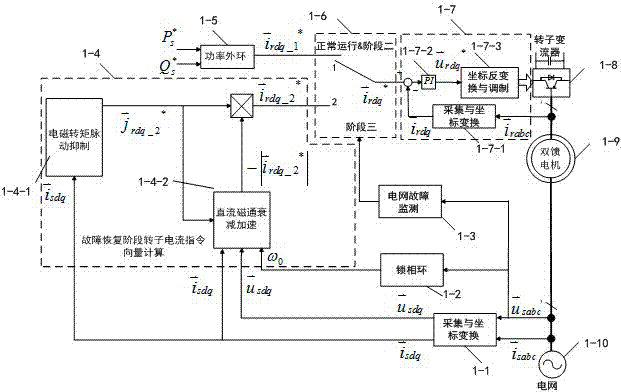
[0025] The method of the present invention includes: through grid fault monitoring, determining grid fault recovery; obtaining the stator voltage vector under the synchronously rotating dq coordinate system through sensor acquisition and coordinate transformation and the stator current vector Obtain the grid angular velocity ω through the phase-locked loop 0 ; Calculate the rotor current command vector in the normal operation of the power grid and the reactive power support stage through the calculation of the outer power loop Simultaneously control rotor current vector during fault recovery phase, grid normal operation phase and reactive power support phase Tracing the rotor current command vector It is characterized in that: in the grid fault recovery stage, the rotor current command vector is switched is the rotor current...


PUM


Abstract

The invention discloses a grid fault recovery control method for an electric generator. The method includes the steps that in the grid fault recovery stage, a rotor current instruction vector is switched to the rotor current instruction vector in the grid fault recovery stage so as to restrain electromagnetic torque pulsation, and meanwhile DC magnetic flux attenuation is accelerated; after being switched out of the grid fault recovery stage, the rotor current instruction vector is switched to the rotor current instruction vector in the grid normal operating stage and the rotor current instruction vector in the reactive power supporting stage; when the rotor current instruction vector in the grid fault recovery stage is calculated, the rotor current instruction vector and a stator current vector are made to be collinear first, then the norm of the rotor current instruction vector in the grid fault recovery stage is obtained, next the norm is substituted into a formula for calculation, and then the rotor current instruction vector in the grid fault recovery stage is obtained. Through the method, the electromagnetic torque pulsation is restrained, switching of flexible faults of a double-fed motor is achieved, and the reliability of a mechanical system is enhanced; because the attenuation of transient DC magnetic flux is accelerated, recovery of power output can be accelerated, the risk that higher electrodynamic potential is inducted on the rotor side under the condition of repeated faults can be avoided as far as possible, rotor currents are limited, and safe operation of a rotor current transformer is guaranteed.

Description

technical field [0001] The invention relates to a power grid control method, in particular to a generator power grid fault recovery control method. Background technique [0002] Wind power technology is a renewable energy technology with good development prospects. The variable-speed constant-frequency wind power generation system has the ability to track the maximum wind energy utilization under wind speed changes, and has been widely used in the past decade. The structure of variable speed constant frequency wind power generation system mainly includes two types of full power converter structure and partial power converter structure. Double-fed wind power generation system is a typical variable speed constant frequency wind power generation system with partial power converter structure. Compared with the variable speed constant frequency wind power generation system with full power converter structure, it has significant cost advantages. However, since the stator of the ...

Claims


Application Information

Patent Timeline
IPC IPC(8): H02P9/00H02P21/00H02J3/38
Inventor 徐德鸿陈文杰陈敏朱楠
Owner ZHEJIANG UNIV
Why Eureka
Try Eureka