
Central vacuum system of foam-plastic forming machine

A vacuum system and molding machine technology, applied in the mechanical field, can solve problems such as the drop of drainage switching pressure and affect product quality, and achieve the effect of ensuring the pass rate

Inactive Publication Date: 2014-07-09
郁震宇
View PDF3 Cites 3 Cited by
  • Summary
  • Abstract
  • Description
  • Claims
  • Application Information

AI Technical Summary

Problems solved by technology

[0002] At present, when the central vacuum system of the foam molding machine on the market is working, there will be a certain pressure drop when the drainage is switched, which will affect the quality of the produced products.

Method used


Image

  • Central vacuum system of foam-plastic forming machine
  • Central vacuum system of foam-plastic forming machine
  • Central vacuum system of foam-plastic forming machine

Examples


Embodiment Construction

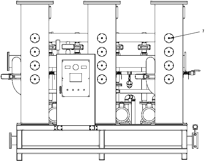
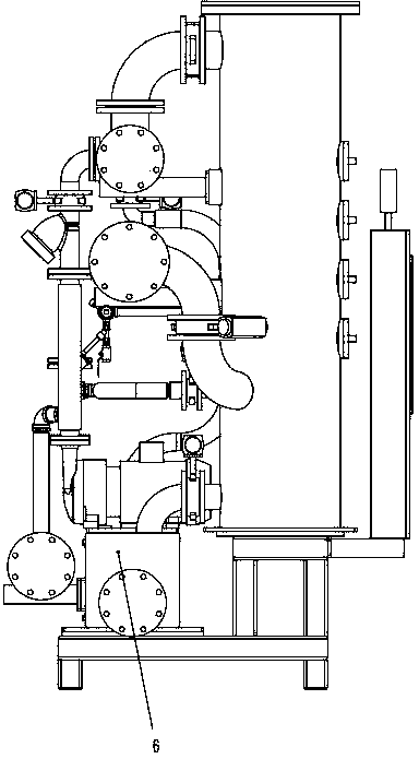
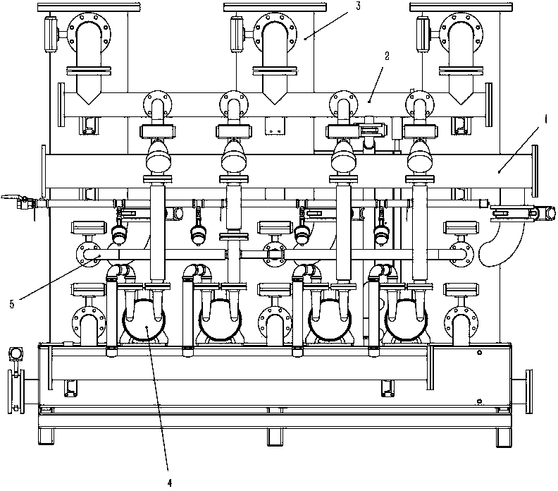
[0013] Such as Figure 1-4 As shown, the central vacuum system includes an intake pipe 1, a distribution pipe 2, a condensation bucket 3, a vacuum pump 4, an auxiliary vacuum pipeline 5, a drainage tank 6 and a sprayer 7, and three condensation buckets 3, one Drainage box 6 and several vacuum pumps 4, air intake pipeline 1 communicates with condensing bucket 3 respectively, the upper part of condensing bucket 3 is connected with distribution pipeline 2 through the upper valve, the bottom of condensing bucket 3 is connected with drainage box 6 through the lower valve, and the middle part of condensing bucket 3 is through The auxiliary vacuum valve is connected with the auxiliary vacuum pipe 5, the vacuum pump 4 is connected with the distribution pipe 2 and the drainage tank 6, and the condensation barrel 3 is equipped with a number of showers 7, which constitute the central vacuum system as a whole.

[0014] When the central vacuum system is working, the gas in the main pipelin...


PUM


Abstract

The invention discloses a central vacuum system of a foam-plastic forming machine. The central vacuum system is characterized in that a rack is provided with three condensing barrels (3), a water discharging box (6) and a plurality of vacuum pumps (4); a gas inlet pipeline (1) is communicated with the condensing barrels (3); the upper parts of the condensing barrels (3) are communicated with a distribution pipeline (2) by upper valves; the lower parts of the condensing barrels (3) are communicated with the water discharging box (6) by lower valves; the middle parts of the condensing barrels (3) are communicated with auxiliary vacuum pipelines (5) by auxiliary vacuum valves; the vacuum pumps (4) are communicated with a distribution pipeline (2) and the water discharging box (6); the condensing barrels (3) are provided with a plurality of sprayers (7); and all the parts form the central vacuum system. The central vacuum system disclosed by the invention has the advantages that the relatively independent condensing barrels are adopted, independent pre-vacuumizing can be adopted for vacuumizing, and no pressure drop of the whole pipeline can be maintained in working, so that the qualification rate of a product is guaranteed.

Description

technical field [0001] The invention relates to the field of machinery, in particular to the central vacuum system of a foam molding machine. Background technique [0002] At present, when the central vacuum system of the foam molding machine on the market is working, there will be a certain pressure drop when the drainage is switched, which will affect the quality of the produced products. Contents of the invention [0003] The purpose of the present invention is to provide a central vacuum system of a foam molding machine, which ensures the pressure in the pipeline and solves the problem of pressure drop in the central vacuum system. [0004] The technical solution adopted by the present invention to solve the technical problem is: the central vacuum system includes an air intake pipeline 1, a distribution pipeline 2, a condensation bucket 3, a vacuum pump 4, an auxiliary vacuum pipeline 5, a drainage tank 6 and a shower 7, and Three condensing barrels 3, a drainage box...

Claims


Application Information

Patent Timeline
IPC IPC(8): B29C44/34
Inventor 郁震宇
Owner 郁震宇
Learn More