Tube Pulling System

A technology for pipe joints and pipe joints to be installed, applied in water conservancy projects, artificial islands, underwater structures, etc., can solve the problems of pipe joint structure damage, increase underwater workload, and large pipe joint volume, so as to avoid damage. , The effect of improving the efficiency of pipe section drawing

Active Publication Date: 2016-02-03
CCCC FIRST HARBOR ENG +1
View PDF8 Cites 0 Cited by
  • Summary
  • Abstract
  • Description
  • Claims
  • Application Information

AI Technical Summary

Problems solved by technology

The pulling system is located on the side beam inside the immersed tube. The disadvantage is that a sealing device needs to be installed on the end sealing wall where the jack piston rod protruding out of the water passes. Secondly, the pulling head at the end of the piston rod needs to be connected to another in the water. pipe joints to increase underwater workload
Due to the large size and heavy weight of the pipe joint, if the jack used for pulling the pipe joint is installed inside the pipe joint, it may cause damage to the pipe joint structure

Method used


Image

  • Tube Pulling System
  • Tube Pulling System
  • Tube Pulling System

Examples


Embodiment Construction

[0027] The specific implementation manners of the present invention will be further described in detail below in conjunction with the accompanying drawings and embodiments. The following examples are used to illustrate the present invention, but are not intended to limit the scope of the present invention.

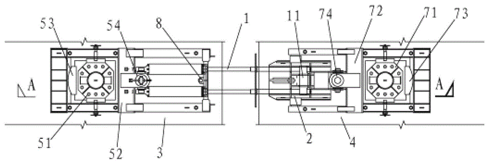
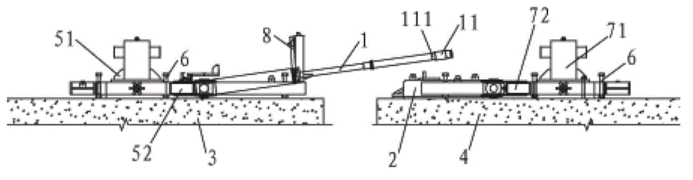
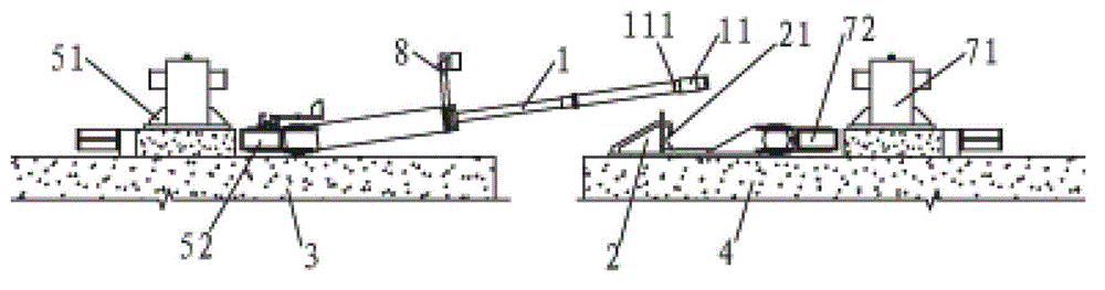
[0028] Such as figure 1 , figure 2 with image 3 As shown, a pipe joint pulling system of the present invention includes a pulling jack 1, a first support, a second support and a hook member 2; the first support and the second support are respectively located at To be installed on the top of the pipe section 3 and the installed pipe section 4, the pulling jack 1 is rotatably connected to the first support, the hook part 2 is rotatably connected to the second support, and the front end of the pulling jack 1 is set There is a pull-on connector 11; the pull-on connector 11 can be overlapped with the hook member 2 through the vertical rotation and lateral expansion and con...


PUM


Abstract

The invention relates to an immersed tube tunnel construction technology and particularly relates to a tube coupling drawing system for immersed tube tunnel construction. The system comprises a drawing jack, a first support, a second support and a hook part. The first support and the second support are arranged at the tops of a to-be-mounted tube coupling and a mounted tube coupling respectively, the drawing jack is connected onto the first support rotatably, the hook is connected onto the second support rotatably, and a drawing connector is arranged at the front end of the drawing jack and can be in lap joint with the hook part through vertical rotation and cross retraction of the drawing jack. According to the system, drawing lamp joint is performed through a drawing component of the drawing jack and the hook part, and the drawing component is arranged at the top of the tube coupling, so that damage to the tube coupling structure is prevented, large tension can be provided, and the tube coupling efficiency is improved; the underwater unmanned operation can be performed through the rotary jack to draw the jack to rise and descend, the drawing jack lap joint speed is fast, and the safety is high.

Description

technical field [0001] The invention relates to the construction technology of immersed tube tunnels, in particular to a pipe joint pulling system used in the construction of immersed tube tunnels. Background technique [0002] The offshore (Hanoi) tunnel consists of multiple immersed tubes. After the immersed tubes are prefabricated in the prefabrication yard, they are floated to the site for docking installation. After the initial positioning and sinking of the immersed tube, the cable is no longer used to move, but the horizontal distance between the two immersed tubes is precisely adjusted through the pulling device, so that the adjacent end faces of the pipe section to be installed and the installed pipe section are in contact, and the sinking is completed. Preliminary docking of tubes. [0003] During the pulling process, the jacks currently used for pulling the pipe joints are generally arranged inside the immersed tube. The pulling system is located on the side bea...

Claims


Application Information

Patent Timeline
Patent Type & Authority Patents(China)
IPC IPC(8): E02D29/073
Inventor 林鸣吴利科关秋枫尹海卿翟世鸿梁萌蒋健刘金秋刘德进宿发强曲俐俐苏长玺王强岳远征周相荣汤慧驰
Owner CCCC FIRST HARBOR ENG
Why Eureka
Try Eureka