
Detecting sensor adjusting device and method and substrate detecting device

A technology for detection sensors and adjustment devices, which is applied to instruments, static indicators, etc., can solve the problems of human resources consumption, high labor costs, and inaccurate adjustments, and achieve the effects of improving detection quality, saving labor costs, and improving detection efficiency

Inactive Publication Date: 2014-07-09
BEIJING BOE OPTOELECTRONCIS TECH CO LTD
View PDF7 Cites 7 Cited by
  • Summary
  • Abstract
  • Description
  • Claims
  • Application Information

AI Technical Summary

Problems solved by technology

[0005] 1) When the level error of the detection sensor exceeds the automatic adjustment range of the substrate detection device, manual rough adjustment is required, especially when replacing a new detection sensor, due to the difference in the detection sensor itself, the intensity of the signal perceived by the detection sensor is also different. Therefore, a manual rough adjustment is required for each replacement, which consumes human resources, high labor costs and low detection efficiency
[0006] 2) When manual rough adjustment is performed, the detected TFT substrate must be able to normally load signals to charge the pixels, and the detected area must not have defects or no signals, so as to ensure the accuracy of the signal strength obtained by the detection sensor in the three preset areas , so as to ensure the accuracy of manual rough adjustment; in the detection process, especially when detecting small-sized TFT products, often due to defects in the TFT substrate, the signal cannot be loaded normally, and the area of ​​the detection sensor is much larger than the area of ​​an internal Panel , the preset detection area is often outside the Panel, and setting the preset detection area is particularly troublesome, and it will affect each other when detecting products of different sizes, resulting in no signal or inaccurate signal in the detection area of ​​the detection sensor, and then As a result, the level adjustment of the detection sensor fails or is inaccurate, and the TFT substrate cannot be detected normally. In other words, the existing technology is only applicable to the scene where the detected area of ​​the TFT substrate has no defects, so the application range is small

Method used


Image

  • Detecting sensor adjusting device and method and substrate detecting device
  • Detecting sensor adjusting device and method and substrate detecting device
  • Detecting sensor adjusting device and method and substrate detecting device

Examples


Embodiment Construction
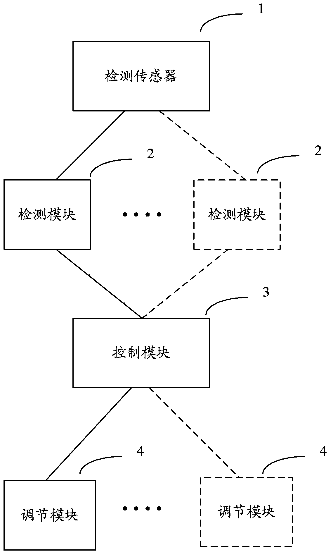
[0047] The basic idea of ​​the present invention is that the substrate detection device includes: a detection sensor, at least one detection module, a control module and at least one adjustment module; wherein, the detection sensor is used to detect the substrate; the detection module is used to detect The levelness of the detection sensor; the control module is used to control the adjustment module to adjust the levelness according to the detection result of the detection module.

[0048] An embodiment of the present invention proposes a detection sensor adjustment device, including: at least one detection module, a control module and at least one adjustment module; wherein,

[0049] The detection module is used to detect the levelness of the detection sensor;

[0050] The control module is configured to control the adjustment module to adjust the level of the detection sensor according to the detection result of the detection module.

[0051] Optionally, the device specifical...


PUM


Abstract

The invention discloses a substrate detecting device which comprises a detecting sensor, at least one detecting module, a control module and at least one adjusting module. The detecting sensor is used for detecting a substrate, the detecting module is used for detecting the levelness of the detecting sensor, and the control module is used for controlling the adjusting module to carry out levelness adjustment according to the detecting result of the detecting module. The invention further correspondingly discloses a detecting sensor adjusting device and method. Through the detecting sensor adjusting device and method and the substrate detecting device, detecting efficiency can be improved, labor cost can be saved, and the application range is large.

Description

technical field [0001] The invention relates to the field of substrate detection, in particular to a detection sensor adjustment device and method, and a substrate detection device. Background technique [0002] In the detection process of Thin Film Transistor (TFT)-Liquid Crystal Display (LCD), the substrate detection equipment needs to keep the detection sensor (Modulator) level to ensure the accuracy of detection results. Specifically, the substrate detection equipment needs to simulate the display principle of TFT-LCD through the detection sensor to perform detection at a distance of 15-20 microns above the TFT substrate. The detection sensor is generally fixed on a substrate detection device (Modulator Mount) with an adjustment function, and each time the TFT substrate is re-detected, the level calibration of the detection sensor must be performed first. [0003] At present, the levelness of the detection sensor is adjusted by combining manual rough adjustment and fine...

Claims


Application Information

Patent Timeline
IPC IPC(8): G09G3/00
Inventor 林子锦赵海生裴晓光马海涛王耀伟
Owner BEIJING BOE OPTOELECTRONCIS TECH CO LTD
Features
  • Generate Ideas
  • Intellectual Property
  • Life Sciences
  • Materials
  • Tech Scout
  • Unparalleled Data Quality
  • Higher Quality Content
  • 60% Fewer Hallucinations
Learn More