IGBT-module installation method

A technology of installation method and installation location, which is applied in the manufacture of electrical components, electric solid devices, semiconductor/solid devices, etc., can solve problems such as module insulation failure, damage to IGBT module subunits in the installation method, module damage, etc., to achieve the goal of solving damage Effect

Inactive Publication Date: 2014-07-09
XIAN YONGDIAN ELECTRIC
View PDF6 Cites 0 Cited by
  • Summary
  • Abstract
  • Description
  • Claims
  • Application Information

AI Technical Summary

Problems solved by technology

[0003] At present, IGBT has been widely used in various industries of the national economy, but the module may be damaged during the actual IGBT module i

Method used


Image

  • IGBT-module installation method
  • IGBT-module installation method
  • IGBT-module installation method

Examples


Example Embodiment

[0026] Experience has shown that the early failure of power semiconductor modules is mainly related to incorrect installation, and incorrect installation will lead to unnecessary high junction temperature, which will greatly reduce the working life of the module. So the correct installation of the module is very important.
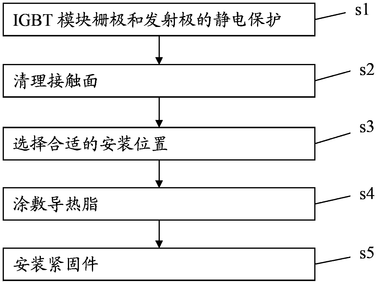
[0027] In view of this, an embodiment of the present invention discloses a method for installing an IGBT module, including:

[0028] s1. Clean the contact surface between the IGBT module and the heat sink;

[0029] s2, select a predetermined installation location;

[0030] s3. Apply thermal grease between the IGBT module and the heat sink;

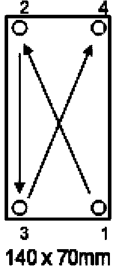
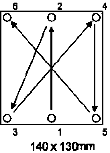
[0031] s4. Install fasteners. All fasteners used to fix the IGBT module should be tightened with a consistent torque. The fasteners should be tightened in diagonal order.

[0032] The above solves the damage caused by the high-power IGBT module during the installation process, and can better improve the reliability of the module...


PUM

PropertyMeasurementUnit
Roughnessaaaaaaaaaa
Flatnessaaaaaaaaaa
Thicknessaaaaaaaaaa

Abstract

The invention discloses an IGBT-module installation method. The method includes: s1: cleaning a contact face of the IGBT module and a cooling fin; s2: selecting a preset installing position; s3: coating a thermal conductive grease between the IGBT module and the cooling fin; s4: installing fasteners and fastening all of the fasteners used for fixing the IGBT module with a consistent torque and fastening the fasteners according to the sequence of diagonal lines. Through the reasonable installation method, a problem of damages caused in an installation process of a large-power IGBT module is solved so that the reliability of the module can be better improved and the reliability of the whole application system can be improved.

Description

technical field [0001] The invention relates to the technical field of semiconductor packaging, in particular to an installation method of an IGBT module. Background technique [0002] IGBT (Insulated Gate Bipolar Transistor), an insulated gate bipolar transistor, is a composite fully-controlled voltage-driven power semiconductor device composed of BJT (bipolar transistor) and MOS (insulated gate field effect transistor), and has a MOSFET The advantages of high input impedance and low conduction voltage drop of GTR. The saturation voltage of GTR is low, the carrying current density is large, but the driving current is large; the driving power of MOSFET is small, the switching speed is fast, but the conduction voltage drop is large, and the current carrying density is small. IGBT combines the advantages of the above two devices, with low driving power and low saturation voltage. It has been more and more widely used in modern power electronics technology, and occupies a domi...

Claims


Application Information

Patent Timeline
IPC IPC(8): H01L21/50H01L21/58
CPCH01L25/50
Inventor 李君伟
Owner XIAN YONGDIAN ELECTRIC
Why Eureka
Try Eureka