Magnetic resonance wireless electric energy transmitting device based on planar magnetic resonant coupling coil structure

A technology of wireless power transmission and magnetic resonance coupling, applied in circuit devices, electrical components, electromagnetic wave systems, etc., can solve the problems of low power transmission efficiency, large space occupation, and high resonance frequency, so as to improve energy conversion efficiency and low resonance frequency. , the effect of parasitic capacitance parameter stabilization

Inactive Publication Date: 2014-07-09
YUANSHUN PHOTOELECTRIC TECH
View PDF7 Cites 4 Cited by
  • Summary
  • Abstract
  • Description
  • Claims
  • Application Information

AI Technical Summary

Problems solved by technology

Different from the electromagnetic induction transmission used by the Qi standard, the electromagnetic resonance transmission does not emit electromagnetic waves, but only forms a non-radiative magnetic field around it, which is similar in strength to the earth's magnetic field, and will not cause adverse effects on the human body and surrounding equipment. The effective transmission distance is tens of centimeters to several meters, but the structure of the existing electromagnetic resonance transmitting coil and electromagnetic resonance receiving coil adopts a space spiral structure. Using this structure makes the resonance frequency higher, occupying a large space, and power transmission low efficiency

Method used


Image

  • Magnetic resonance wireless electric energy transmitting device based on planar magnetic resonant coupling coil structure
  • Magnetic resonance wireless electric energy transmitting device based on planar magnetic resonant coupling coil structure
  • Magnetic resonance wireless electric energy transmitting device based on planar magnetic resonant coupling coil structure

Examples


Embodiment Construction

[0029] The present invention will be further described below in conjunction with the accompanying drawings and specific embodiments, but not as a limitation of the present invention.

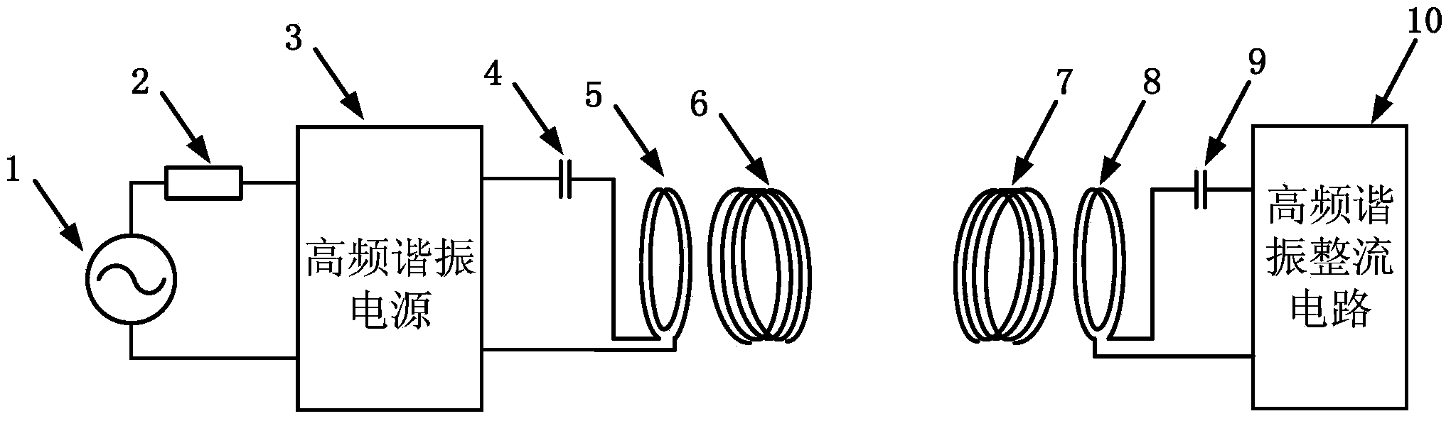
[0030] Such as figure 1 As shown, a magnetic resonance wireless power transfer device based on a planar magnetic resonance coupling coil structure, including

[0031] - an input power source 1 having an output terminal,

[0032] - a high-frequency resonant power supply 3 having an input terminal and an output terminal;

[0033] - High frequency resonant rectification circuit 10;

[0034] The input power supply 1 is connected to one end of the AC power load 2, and the other end of the AC power load 2 is connected to the input end of the high-frequency resonant power supply 3;

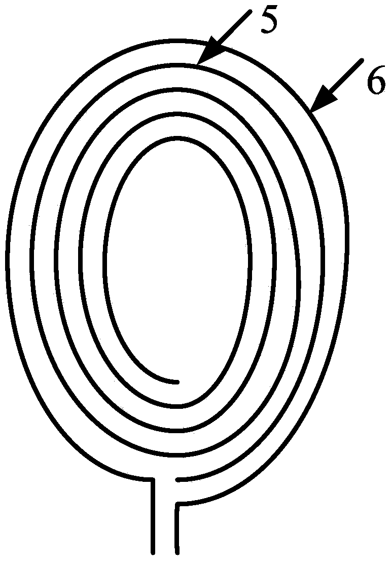
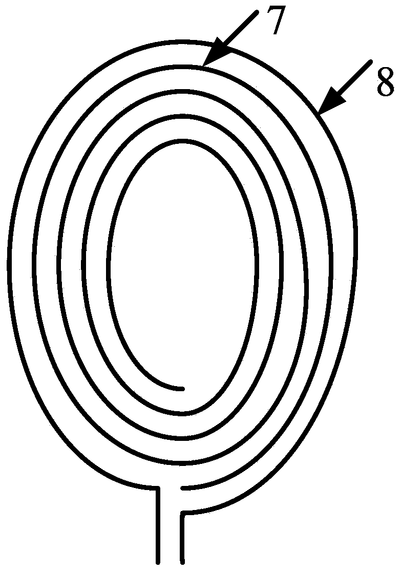
[0035] It also includes a power supply coil 5, an electromagnetic resonance transmitting coil 6, an electromagnetic resonance receiving coil 7 and a load coil 8, the power supply coil 5 is connected to the output end of...


PUM


Abstract

The invention relates to a magnetic resonance wireless electric energy transmitting device, in particular to a magnetic resonance wireless electric energy transmitting device based on a planar magnetic resonant coupling coil structure. The magnetic resonance wireless electric energy transmitting device comprises an input source provided with the output end, a high-frequency resonance power source provided with the input end and the output end and a high-frequency resonance rectifying circuit. Compared with the prior art, a power source coil and an electromagnetic resonance emitting coil are wound mutually to form a plane structure coil, an electromagnetic resonance receiving coil and a load coil are wound mutually to form a plane structure coil, space occupancy is lowered, resonance frequency is reduced, and energy transmitting efficiency is improved.

Description

technical field [0001] The invention relates to a magnetic resonance wireless power transmission device, in particular to a magnetic resonance wireless power transmission device based on a planar magnetic resonance coupling coil structure. Background technique [0002] Wireless power transmission technology, also known as non-contact power transmission technology, was proposed by the famous Serbian-American electrical engineer and physicist Nikola Tesla as early as 1890. Wireless power transmission technology uses the principle of electromagnetic wave induction and related AC induction technology, and uses corresponding coils at the sending and receiving ends to send and receive induced AC signals for power transmission. According to the different principles of power transmission, wireless power transmission can be Divided into: electromagnetic induction, electromagnetic resonance and electromagnetic radiation. [0003] The International Wireless Charging Alliance released ...

Claims


Application Information

Patent Timeline
Patent Type & Authority Applications(China)
IPC IPC(8): H02J17/00H02J50/12
Inventor 童立青佘远汉汪思薇
Owner YUANSHUN PHOTOELECTRIC TECH
Why Eureka
Try Eureka