Radio-frequency transceiver and radio-frequency transceiving method
A technology of radio frequency transceiver and radio frequency transmission, applied in wireless communication, space transmit diversity, electrical components, etc.
- Summary
- Abstract
- Description
- Claims
- Application Information
AI Technical Summary
Problems solved by technology
Method used
Image

Examples
specific Embodiment 1
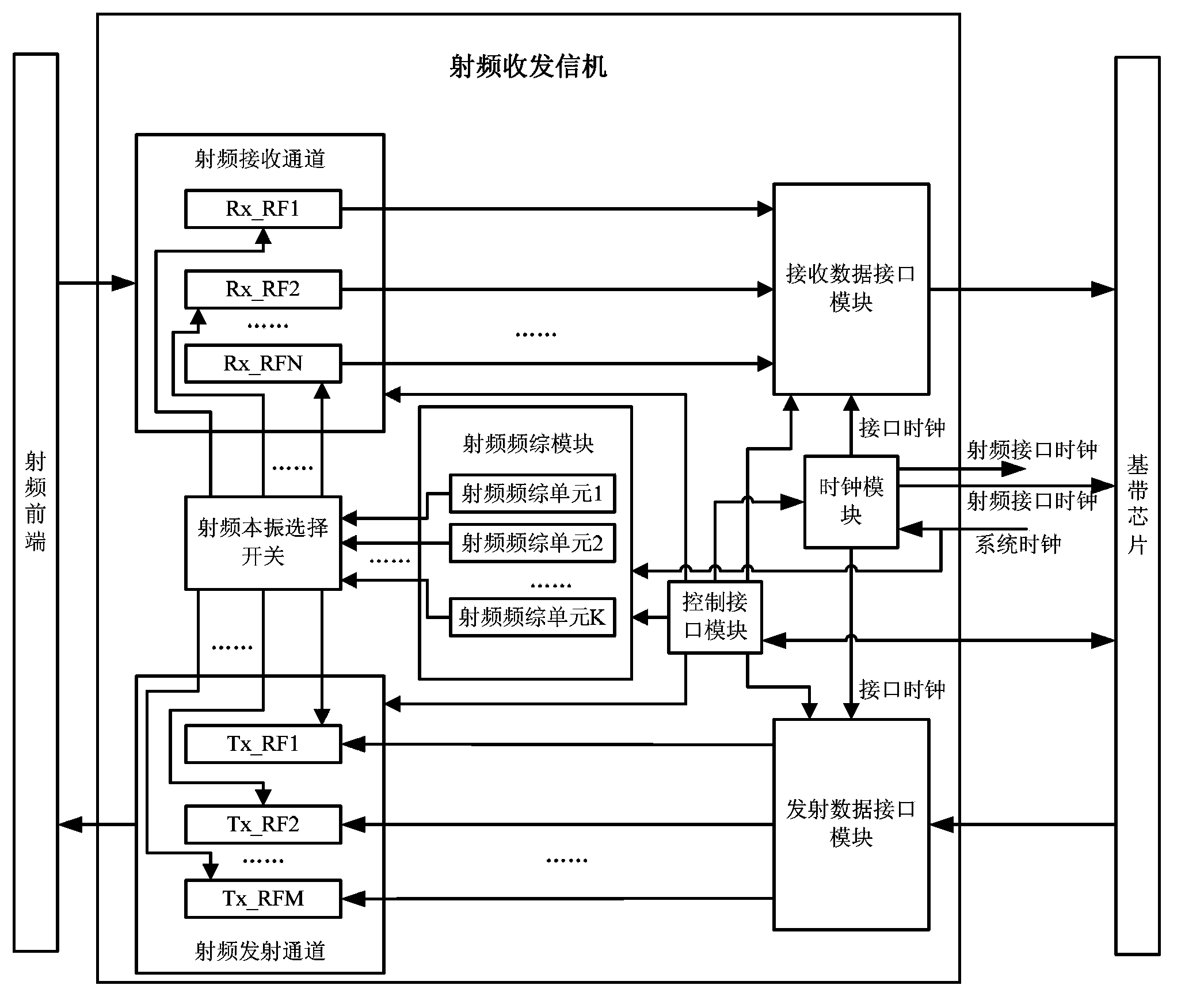
[0053] This embodiment is a preferred implementation of the radio frequency transceiver of the present invention; the overall structure is as follows figure 1 shown, including:
[0054] N radio frequency receiving channels, Rx_RF1~Rx_RFN; M radio frequency transmitting channels Tx_RF1~Tx_RFM;
[0055] Rx_RFn is connected to the radio frequency front end, and receives the downlink radio frequency signal from the radio frequency front end;
[0056] Tx_RFm is connected to the radio frequency front end, and transmits an uplink radio frequency signal to the radio frequency front end;
[0057] Among them, n is the serial number of the radio frequency receiving channel, n=1, 2,..., N; m is the serial number of the radio frequency transmitting channel, m=1, 2,..., M;
[0058] Among them, N and M can be set according to the actual needs of the terminal:
[0059] If the terminal needs to be able to support the maximum number of carriers and the maximum number of MIMO radios to transm...
specific Embodiment 2
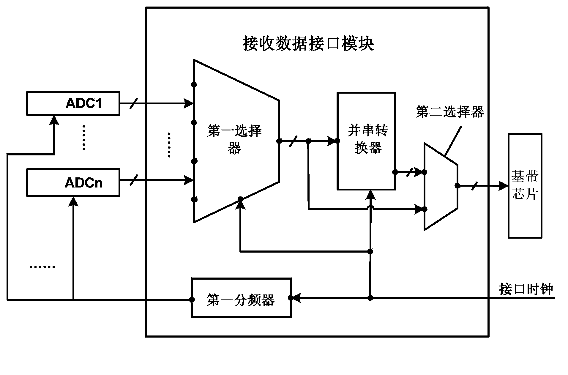
[0073] This embodiment is a preferred implementation of the receiving data interface module of the specific embodiment 1 radio frequency transceiver, and the receiving data interface module includes:
[0074] N analog-to-digital converters ADC1-ADCN;
[0075] The first selector; the first selector is preferably a multi-input single-output multiplexer with N-way input and single-way output, and the number of digits of each input and the number of outputs are not greater than the number of digits of ADCn;
[0076] The input terminal of ADCn is connected to Rx_RFn, the output terminal of ADCn is connected to the input terminal n of the first selector; the output terminal of the first selector is connected to the baseband chip;
[0077] The ADCn performs analog-to-digital conversion on the downlink analog signal output by Rx_RFn to generate a downlink digital signal; the first selector strobes each ADCn in turn, and sends the downlink digital signal output by the gated ADCn to the...
specific Embodiment 3
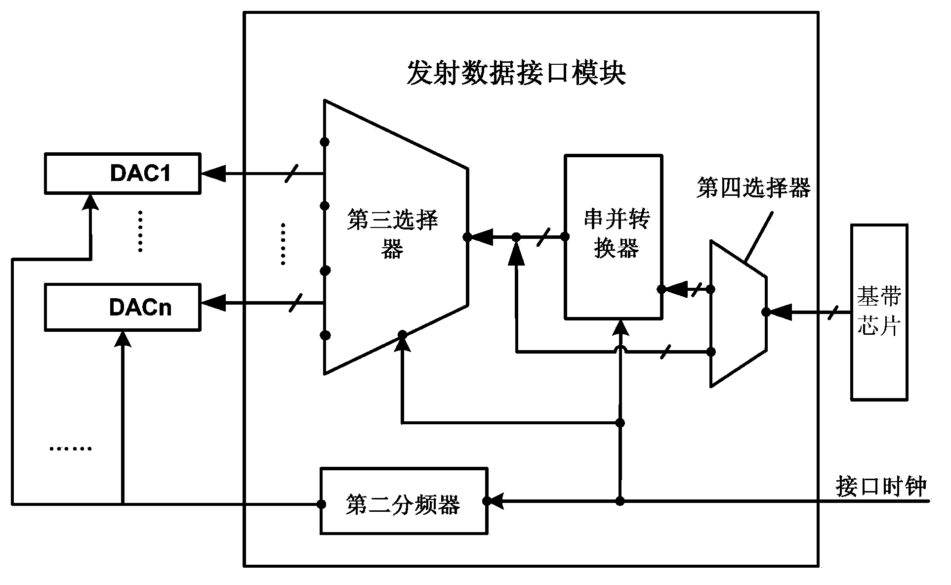
[0091] This embodiment is a preferred implementation of the transmission data interface module of the radio frequency transceiver of specific embodiment 1, and the transmission data interface module includes:
[0092] M digital-to-analog converters DAC1-DACM;
[0093] The third selector; the third selector is preferably a single-input multiple-output multiplexer with single-way input and M-way output, and the number of bits output by each way and the number of bits input are not less than the number of bits of DACm;
[0094] The input end of DACm is connected to Tx_RFm, the input end of DACm is connected to the output end m of the third selector; the input end of the third selector is connected to the baseband chip;
[0095] The third selector selects each DACm sequentially, and the selected DACm performs digital-to-analog conversion on the uplink digital signal output from the baseband to generate an uplink analog signal and send it to Tx_RFm.
[0096] In this example,
[0...
PUM
 Abstract
Description
Claims
Application Information
 - R&D
- Intellectual Property
- Life Sciences
- Materials
- Tech Scout
- Unparalleled Data Quality
- Higher Quality Content
- 60% Fewer Hallucinations
Browse by: Latest US Patents, China's latest patents, Technical Efficacy Thesaurus, Application Domain, Technology Topic, Popular Technical Reports.
© 2025 PatSnap. All rights reserved.Legal|Privacy policy|Modern Slavery Act Transparency Statement|Sitemap|About US| Contact US: help@patsnap.com