A sizing beam creel

A technology of warp creel and warp beam, which is applied in the field of sizing warp creel, which can solve the problems of inability to drive, reduce production efficiency, twisting, etc., and achieve the effects of saving drying steps, improving production efficiency and reducing production cost

Active Publication Date: 2016-10-26
JIANGSU PINYTEX TEXTILE DYEING & FINISHING
View PDF9 Cites 0 Cited by
  • Summary
  • Abstract
  • Description
  • Claims
  • Application Information

AI Technical Summary

Problems solved by technology

[0002] Sizing warp creel in the prior art such as figure 1 As shown, the warp creel of ordinary sizing machines is generally only suitable for the production of co-dyeing varieties, but not the production of shaft-dyed varieties. It can meet the production of shaft-dyed varieties, but it is powerless for high-count and high-density compact-spun shaft-dyed varieties due to the large distance between axes (900mm).
After pre-baking the surface of the shaft-dyed warp beam, although the twisting phenomenon of the surface warp yarn can be improved, if the inner yarn is slowed down for too long during the production process, serious twisting will still occur, and even the machine cannot be driven. serious consequences
However, after beam dyeing, a long drying process is required, which not only greatly reduces production efficiency, but also consumes a large amount of steam energy and increases production costs.

Method used


Image

  • A sizing beam creel
  • A sizing beam creel

Examples


Embodiment 1

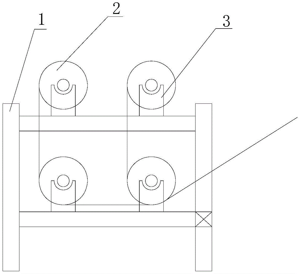
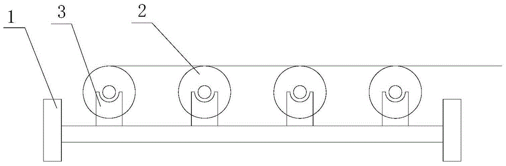
[0014] Such as figure 2 Shown is a schematic diagram of the structure of the sizing beam frame of the present application, including a base 1 and several pairs of frames 3 installed on the base 1 for supporting the warp beam 2, and the plurality of pairs of frames 3 are arranged parallel to each other in the same plane , and the height is equal, and the distance between the warp beams 2 on the adjacent pair of frame bodies 3 is 450mm. In the present application, the frame body 3 supporting the warp beam is arranged in parallel in the same plane, and the height of the frame body 3 is equal, and the distance between the two axes of warp beams on the adjacent pair of frame bodies 3 is 450mm, compared to figure 1 The traditional upper and lower structure of the warp creel can effectively shorten the distance between the warp beams, and can effectively prevent the warp yarns from being twisted together. It has been proved by experiments that the warp yarns will not be twisted when...

Embodiment 2

[0016] As an improvement of Embodiment 1, there are slide rails on both sides of the base 1 that are perpendicular to the axial direction of the warp beam 2, and the frame body 3 is slidably connected to the base 1 through the slide rails. The body 3 is locked on the locking device on the base 1. Can adjust the distance between the warp beams 2 according to the diameter of the warp beam 2 or the warp yarn thickness on the warp beam 2 before driving like this, drive again after locking, shorten the warp beam spacing as far as possible.


PUM


Abstract

The invention provides a slasher creel. According to the technical scheme, the slasher creel comprises a base and a plurality of pairs of rack bodies which are mounted on the base and are used for supporting warp beams. The pairs of rack bodies are arranged in the same plane in parallel, and the heights of the pairs of rack bodies are the same. According to the slasher creel, the rack bodies which are used for supporting the warp beams are arranged in the same plane in parallel, the heights of the rack bodies are the same, the distances between the warp beams can be effectively shortened compared with a traditional beam creel of an up-down layer structure in the first map, and warps can be effectively prevented from being twisted together. Through verification of experiments, under the condition that the wraps are wet (is not dried after dewatering), the condition of warp twisting does not happen, the drying step which has to be executed after warp dyeing is omitted, and production efficiency is improved. The slasher creel has the advantages that the distances of the warp beams can be effectively shortened, the warps can not be twisted together without being dried, the drying step is omitted, and the production efficiency is improved.

Description

technical field [0001] The invention relates to a sizing creel. Background technique [0002] Sizing warp creel in the prior art such as figure 1 As shown, the warp creel of ordinary sizing machines is generally only suitable for the production of co-dyeing varieties, but not the production of shaft-dyed varieties. It can satisfy the production of shaft-dyed varieties, but it is powerless for high-count and high-density compact-spun shaft-dyed varieties due to the large interaxial distance (900mm). After pre-baking the surface of the shaft-dyed warp beam, although the twisting phenomenon of the surface warp yarn can be improved, if the inner yarn is slowed down for too long during the production process, serious twisting will still occur, and even the machine cannot be driven. serious consequences. However, after beam dyeing, a long drying process is required, which not only greatly reduces the production efficiency, but also consumes a large amount of steam energy, which...

Claims


Application Information

Patent Timeline
Patent Type & Authority Patents(China)
IPC IPC(8): D06B23/04
Inventor 谢斌
Owner JIANGSU PINYTEX TEXTILE DYEING & FINISHING
Why Eureka
Try Eureka