
Automatic powder wall machine

A plastering machine, automatic technology, applied in the direction of construction, building construction, etc., can solve problems such as the decline of plastering quality, unsatisfactory, and the change of the distance between the end and the wall surface, so as to achieve the improvement and guarantee of the flatness of the wall surface and the quality of the wall surface Quality and work efficiency, the effect of ensuring the continuity of feeding

Inactive Publication Date: 2016-08-24
ZHENGZHOU HUAZHONG CONSTR MACHINERY CO LTD
View PDF5 Cites 1 Cited by
  • Summary
  • Abstract
  • Description
  • Claims
  • Application Information

AI Technical Summary

Problems solved by technology

However, the current feeding system uses a mortar pump. The supply of mortar is intermittent, and the mop head cannot work continuously. Meet the needs of actual production
[0004] After painting a section of wall in the house, it is necessary to move the frame horizontally to continue painting the adjacent section of wall. At present, manual movement is time-consuming and labor-intensive. Some plastering machines use universal wheels on the front side, but the universal wheels cannot Will cause the distance between the trowel and the wall to change, so that the quality of the painting will be affected

Method used


Image

  • Automatic powder wall machine
  • Automatic powder wall machine
  • Automatic powder wall machine

Examples


Embodiment approach 1

[0046] Such as Figure 7 As shown, the swing cylinder inlet 6 is connected with the swing mechanism 4, the swing mechanism 4 includes a swing rod 12 and two second hydraulic cylinders 13, the rear side of the hopper 2 is connected with a swing shaft 46, and the upper end of the swing rod 12 is connected with the swing shaft 46. The hopper 2 is rotatably connected, and the lower end of the swing rod 12 is fixedly connected with the swing cylinder inlet 6 . The swing cylinder outlet 7 and the swing shaft 46 are rotatably connected to the front and rear sides of the hopper 2, and the centerlines of the swing cylinder outlet 7 and the swing shaft 46 coincide. The swing shaft 46 and the connection between the swing cylinder outlet 7 and the hopper 2 are all provided with bearings.

[0047] The upper end of the swing lever 12 is integrally connected with a push rod 51, the push rod 51 coincides with the center line of the swing rod 12, and the both sides of the push rod 51 are resp...

Embodiment approach 2

[0050] Since the swing rod 12 adopted in the first embodiment initially has an included angle when it swings to both ends, and the force is not good, the second embodiment can be adopted.

[0051] Such as Figure 8 As shown, the swing mechanism 4 cancels the two second hydraulic cylinders 13, the hydraulic motor 47 replaces the second hydraulic cylinder 13 to provide power, the swing shaft 46 is reserved, the swing rod 12 retains a section connected to the swing cylinder 3, and the lower end of the swing rod 12 It is connected to the end of the swing cylinder 3, and the upper end of the swing rod 12 is connected to the swing shaft 46. The difference is that the swing mechanism 4 includes a hydraulic motor 47, an active reversing wheel 48, a passive reversing wheel 49, two traction ropes 50, 51, the hydraulic motor 47 is equipped with an active reversing wheel 48, the upper end of the swing lever 12 is coaxially connected with the passive reversing wheel 49, the passive reversi...


PUM


Abstract

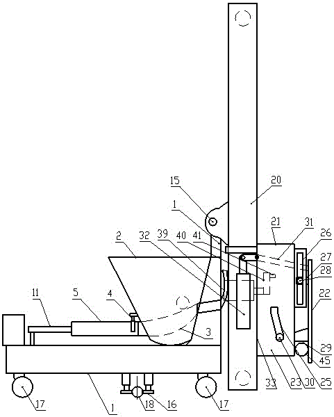
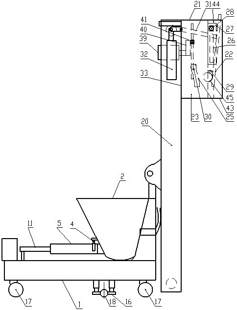
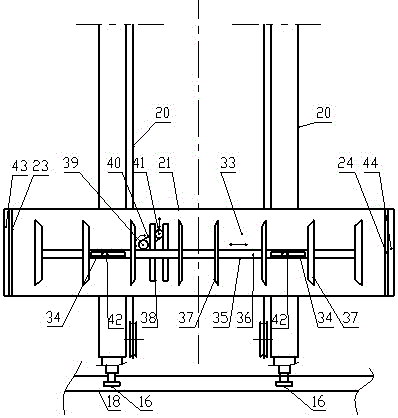
An automatic wall plastering machine comprises a feeding system and a plastering head. The feeding system comprises a frame, a sliding frame and a hopper. The sliding frame is connected to the front side of the frame, and the hopper is connected to the frame. The plastering head of the wall plastering machine comprises a plastering head shell which is of a rectangular shell provided with an opening in the front side, and a left-side plate and a right-side plate are respectively arranged on the left side and the right side of the plastering head shell which is mounted on the sliding frame. The plastering head comprises a tongue plate vertically connected to the front side of the plastering head shell and a vertical moving mechanism driving the tongue plate to move vertically, the front side face of the tongue plate is provided with a plane, and dust leakage outlets are formed in the tongue plate. A swaying cylinder swing back and forth can be communicated with two feeding cylinders respectively, and the feeding cylinders not communicated with the swaying cylinder absorb mortar, so that continuous and sufficient amount of fed materials is realized, feeding continuity at the position of the plastering head can be guaranteed, and quality of wall plastering and operation efficiency are ensured.

Description

technical field [0001] The invention relates to the field of construction machinery, in particular to a plastering machine. Background technique [0002] The plastering machine is used to paint the walls of buildings. It includes a frame, a sliding frame and a mop head. The sliding frame is connected to the front side of the frame. Movement, the shape of the wipe head is generally a cuboid, and the inside of the wipe head is a mortar chamber, which is located in the middle of the wipe head. The mortar in the hopper is sent to the mortar chamber by the mortar pump through the hose. However, the stroke of the mortar pump is small and driven by the crankshaft. However, when the current mop head is in use, if it is to paint the top corner of the wall, it will not be able to be applied, leaving an area that cannot be painted, and the top corner will not be pressed firmly. [0003] The powder wall machine also includes a feeding system arranged on the frame. The feeding system ...

Claims


Application Information

Patent Timeline
Patent Type & Authority Patents(China)
IPC IPC(8): E04F21/08
Inventor 宋发才
Owner ZHENGZHOU HUAZHONG CONSTR MACHINERY CO LTD
Learn More