
Power slip

A technology of power slips and slips, which is applied to drilling equipment, earthwork drilling, drill pipes, etc., can solve the problems of large replacement parts, small replacement parts, low work efficiency, etc. The effect of small amount and high drilling efficiency

Active Publication Date: 2014-07-16
SICHUAN HONGHUA PETROLEUM EQUIP
View PDF7 Cites 6 Cited by
  • Summary
  • Abstract
  • Description
  • Claims
  • Application Information

AI Technical Summary

Problems solved by technology

[0006] The purpose of the present invention is to overcome the disadvantages of the prior art that the power slips are applied to pipe strings with different diameters and the number of replacement parts is large and the work efficiency is low, and to provide a kind of replacement parts for pipe strings with different pipe diameters. Power slips with small size and high working efficiency

Method used


Image

  • Power slip
  • Power slip
  • Power slip

Examples


Embodiment 1

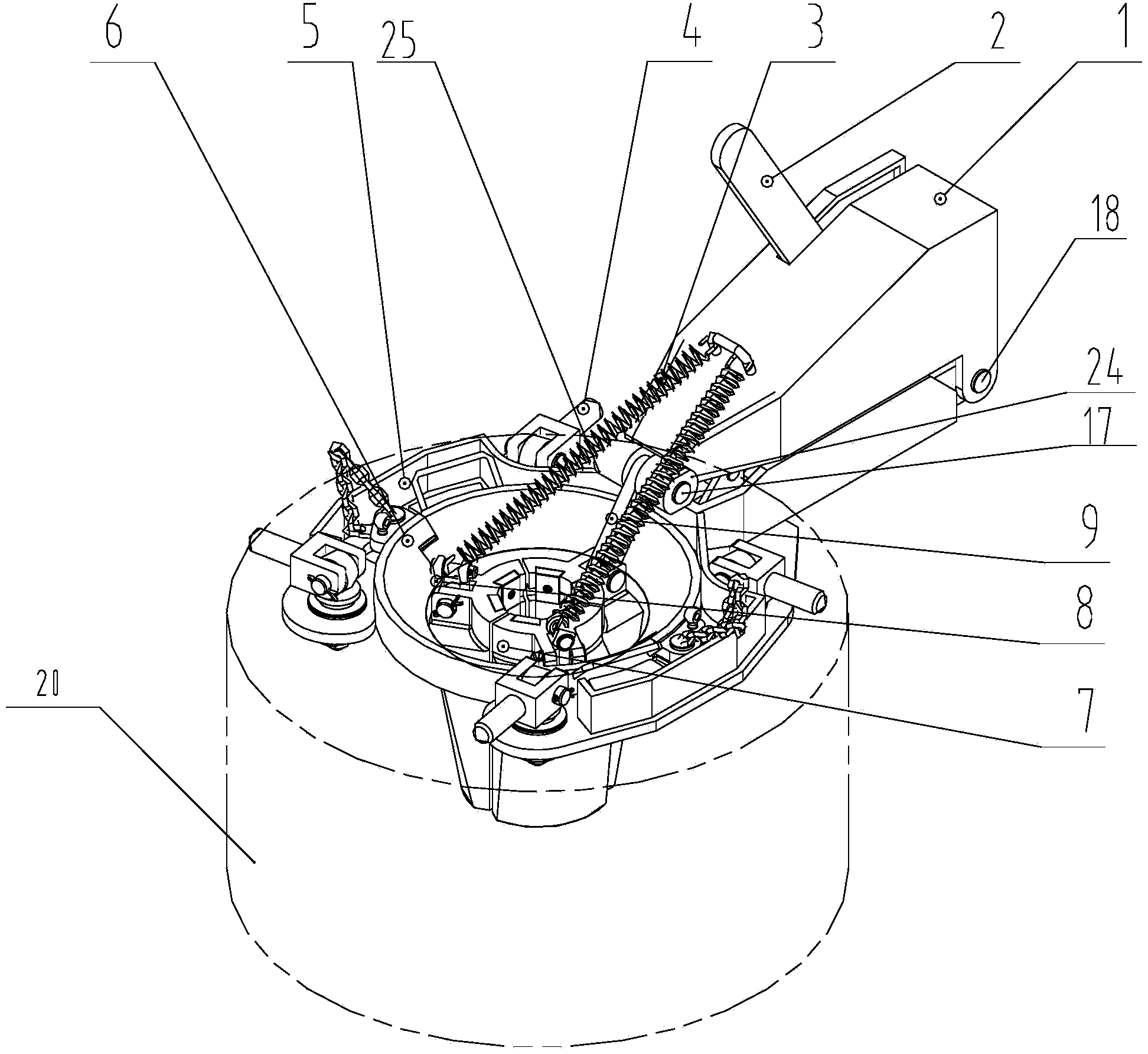
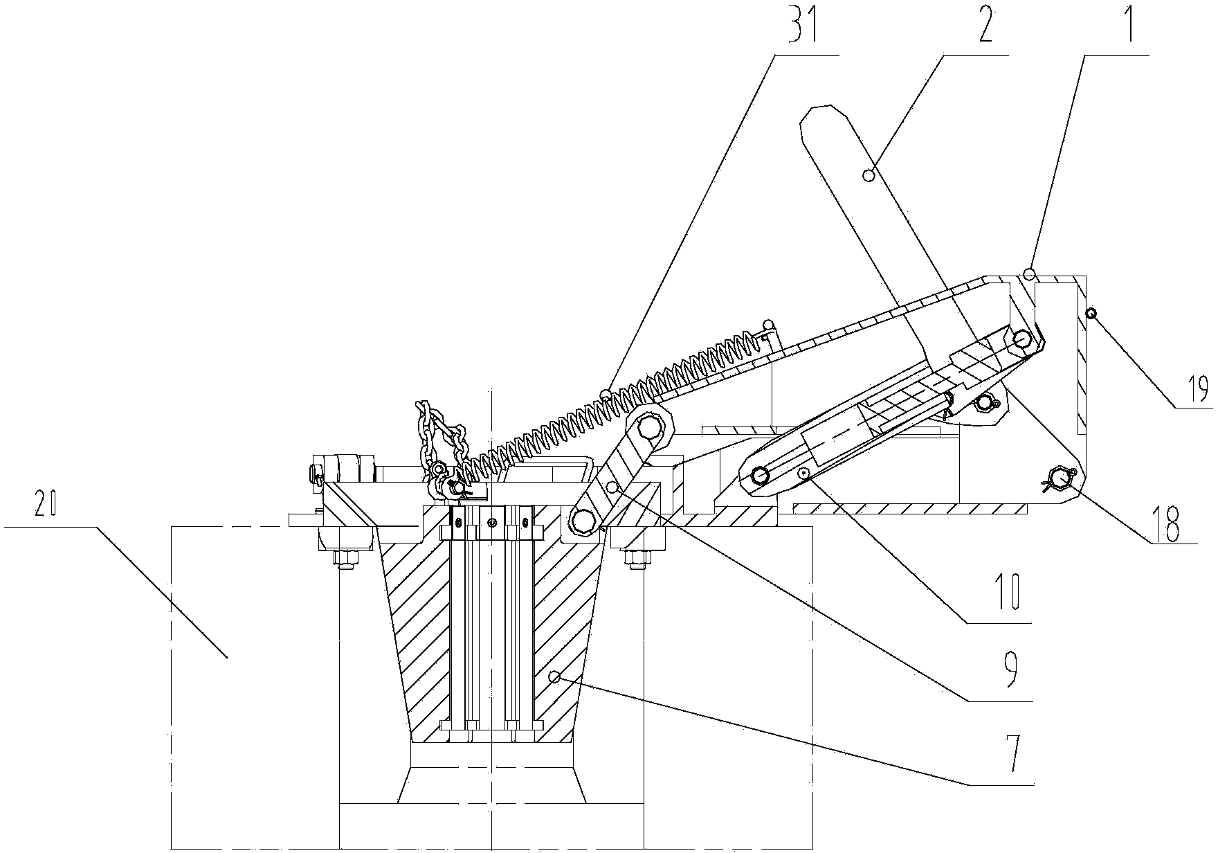
[0056] Such as figure 1 As shown, a power slip includes a base 5 connected to a turntable 20 through a quick connection device 4 .

[0057] The schematic diagram of the three-dimensional structure of the base 5 is as Figure 5 shown. The base 5 is provided with four turntable connection holes 52, and the quick connection device 4 passes through the turntable connection holes 52 to fix the base 5 in the corresponding pin hole on the turntable 20. The pin holes of the turntable 20 are self-contained pin holes, and no additional processing is required. ; The base 5 is also provided with a chute 51 , the chute 51 is used to position the slip body guide 6 installed on the base 5 .

[0058] Figure 6 , Figure 7 It is a schematic structural view of the quick connection device 4 used to fix the base 5, Figure 6 It is a structural schematic diagram of the quick connection device 4 in a loosened state, Figure 7 It is a structural schematic diagram of the quick connection device...

Embodiment 2

[0067] The power slips in this embodiment are multi-piece casing slips. The difference between the multi-piece sleeve slips of this embodiment and the three-piece power slips disclosed in Embodiment 1 is that:

[0068] Replace the three-piece slips 7 and the lifting rod 9 of the power slips in Example 1, and assemble them as follows: Figure 16 The U-shaped lifting ring 12 and the multi-piece casing slip 14 are shown.

[0069] Figure 16 The U-shaped lifting ring 12 shown includes a U-shaped piece 1201 and a U-shaped positioning connecting piece.

[0070] The U-shaped piece 1201 is provided with 3 small holes, and the 3 small holes are located at the bottom of the U-shaped piece and the two ends of the open end of the U-shaped piece respectively. One ends of the three small chains 13 pass through the small holes and are respectively fixed on the U-shaped pieces, and the other ends of the small chains 13 are respectively connected to the multi-piece casing slips 14 through s...


PUM


Abstract

The invention discloses a power slip, and belongs to the technical field of petroleum drilling corollary equipment. The power slip comprises a base, a slip body guide device is arranged on the base, and a locating sliding block is arranged on the outer side face of the slip body guide device. A sliding groove matched with the locating sliding block is arranged on the base, and the locating sliding block slides in or slides off the sliding groove in the circumferential direction. After the locating sliding block enters the sliding groove and is located, the axial movement of the slip body guide device is limited. After the locating sliding block leaves the sliding groove, the slip body guide device can be demounted from the base. Through the power slip with the structure, the slip body guide device is detachably mounted on the base, only the slip body guide device, a turntable bushing and the slip which are matched with tubular columns are replaced when the tubular columns with the different pipe diameters are replaced, the workload for mounting the slip is small, and the working efficiency of well drilling is high.

Description

technical field [0001] The invention relates to a power slip, which belongs to the technical field of supporting equipment for petroleum drilling. Background technique [0002] Slips are tools used in oil drilling to stick and hang drill strings in wells. At present, tripping and casing operations mainly use double-elevator switching or single-elevator combined with portable slips. Both the double-elevator method and the portable slips have problems such as high work intensity and low work efficiency. [0003] In the prior art, the power slips include a base, the base is installed on the turntable, the turntable is provided with a turntable centering, and the base is provided with a slip body guiding device that cooperates with the turntable centering, and the base and the slip body guiding device are integrated formula structure. When the slips are lowered, the slip body guiding device is introduced into the center of the turntable on the turntable to clamp the pipe strin...

Claims


Application Information

Patent Timeline
Patent Type & Authority Applications(China)
IPC IPC(8): E21B19/10
Inventor 夏宏克姚宇翔单代伟罗锐
Owner SICHUAN HONGHUA PETROLEUM EQUIP
Learn More