Fuel injector and fuel injection device using same

A fuel injector and injection port technology, which is applied to fuel injection devices, charging systems, machines/engines, etc., can solve problems such as damage to the movable core stator core, and achieve the effect of reducing changes and limiting damage.

Active Publication Date: 2017-06-06
DENSO CORP
View PDF8 Cites 0 Cited by
  • Summary
  • Abstract
  • Description
  • Claims
  • Application Information

AI Technical Summary

Problems solved by technology

In addition, damage to the movable core or the stator core may occur

Method used


Image

  • Fuel injector and fuel injection device using same
  • Fuel injector and fuel injection device using same
  • Fuel injector and fuel injection device using same

Examples


no. 1 example

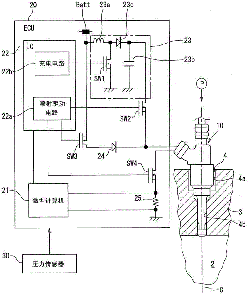
[0021] Such as figure 1 As shown in , a fuel injector 10 is mounted on an ignition type internal combustion engine and injects fuel directly into a combustion chamber 2 of the internal combustion engine. For example, the internal combustion engine may be a gasoline engine. Specifically, an attachment hole 4 for inserting a fuel injector 10 is axially provided in a cylinder head (cylinder head) 3 along an axis C of the cylinder. Fuel supplied to the fuel injector 10 is pumped by a fuel pump P driven by an internal combustion engine.

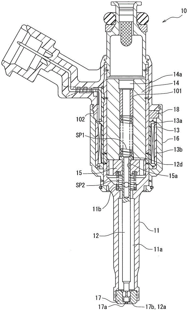
[0022] Such as figure 2 As shown in , the fuel injector 10 includes a body 11 , a valve body 12 , a first coil 13 , a stator core 14 , a movable core 15 and a housing 16 . The body 11 is made of a magnetic metal material and includes a fuel passage 11a. The body 11 forms a seated surface 17b and an injection port 17a. The valve body 12 abuts on the seating surface 17b or is separated from the seating surface 17b. Fuel is injected through th...

no. 2 example

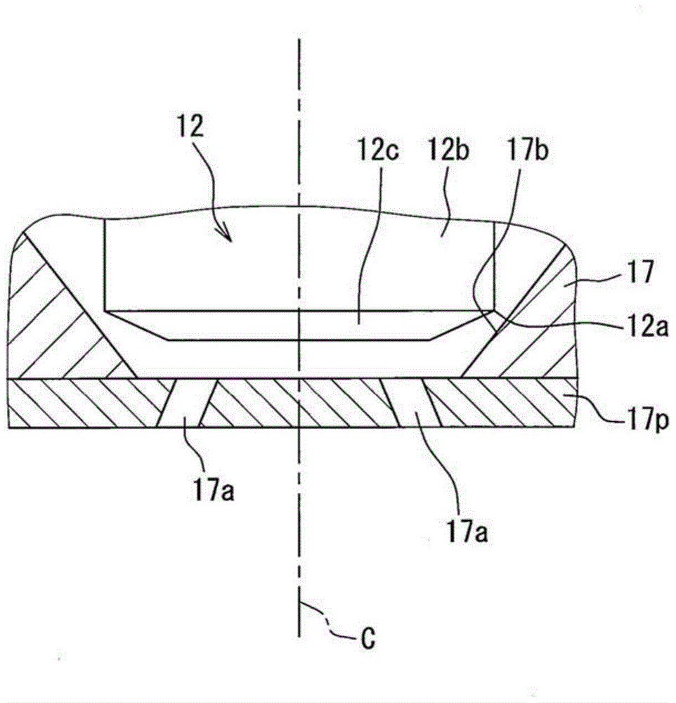
[0093] According to the first embodiment, the boundary between the main body 12b and the end portion 12c functions as the seating surface 12a. According to the second embodiment, as Figure 8 As shown in , the end 12e is generally spherical and extends from the main body 12b toward the injection port 17a. Furthermore, that portion of the end portion 12e which abuts against the seating surface 17b functions as the seating surface 120a. In other words, the seating surface 120a replaces the seating surface 12a. Such as Figure 8 As shown in , the seating surface 120a has a curved portion. According to the first embodiment, the seating surface 12a has an inclined section.

[0094] The ratio of the fuel pressure valve closing force Ffo to the fuel pressure valve closing force Ffc is called a throttle ratio Tr.

[0095] Tr=Ffo / Ffc

[0096] Since the fuel pressure valve closing force Ffo decreases according to an increase in the throttle ratio Tr, it is possible to limit the gr...


PUM


Abstract

A fuel injector includes a valve body moved together with a movable core and opening an injection port, and an elastic-force applying portion being elastically deformable according to a movement of the valve body to apply an elastic force to the valve body in a valve-closing direction. An elastic coefficient of the elastic-force applying portion is set to meet a condition that Ffc−Ffo≰L×K. In this case, a fuel-pressure valve-closing force of when the valve body is closed is referred to as Ffc, and the fuel-pressure valve-closing force of when the valve body is completely opened is referred to as Ffo. A movement distance of the valve body from a time point that the valve body is closed to a time point that the valve body is completely opened is referred to as L. The elastic coefficient is referred to as K.

Description

technical field [0001] The present invention relates to a fuel injector that is opened or closed by electromagnetic force and a fuel injection device using the fuel injector. Background technique [0002] JP-2011-214536A (US 2013 / 0087639A1) discloses a fuel injector that includes a stator core that generates electromagnetic force by energizing a coil, a movable core that moves by electromagnetic force, and a The valve body that moves together and opens the injection port. The elastic force of the spring and fuel pressure are applied to the valve body in a valve closing direction. When the attractive force (valve opening force) according to the energization of the coil becomes larger than the closing force corresponding to the elastic force and the fuel pressure, the valve body initiates the valve opening operation. [0003] When the coil is energized to open the valve body, the movable core moves to the stator core and collides with the stator core. When the collision spe...

Claims


Application Information

Patent Timeline
Patent Type & Authority Patents(China)
IPC IPC(8): F02M51/06
CPCF02M51/0664F02M51/0675F02M61/205
Inventor 今井启太伊藤荣次
Owner DENSO CORP
Why Eureka
Try Eureka