
A pilot-operated power station gate valve

A pilot-operated, gate valve technology, applied in the direction of sliding valves, valve devices, engine components, etc., can solve the problems of hidden welding seams and large volume, and achieve the effect of compact structure, small volume, and reduced opening torque

Active Publication Date: 2016-06-29
NANTONG POWER STATION VALVE
View PDF7 Cites 0 Cited by
  • Summary
  • Abstract
  • Description
  • Claims
  • Application Information

AI Technical Summary

Problems solved by technology

But it also has certain defects: the structure is an external pilot valve structure, the overall product is large in size, and it needs to be welded on the valve body, so there are hidden dangers of welding seam

Method used


Image

  • A pilot-operated power station gate valve
  • A pilot-operated power station gate valve
  • A pilot-operated power station gate valve

Examples


Embodiment Construction

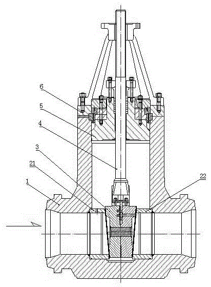
[0023] Such as figure 1 As shown, it mainly includes a valve body 1, a left valve seat 21, a right valve seat 22, a gate plate 3, a valve stem 4, a valve cover 5, and a gland 6.

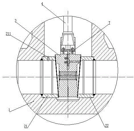
[0024] The left valve seat 21 and the right valve seat 22 are welded on the liquid inlet side and the liquid outlet side of the flow channel at the bottom of the valve body 1, and a gate plate 3 that can cooperate with the valve seat 2 to realize the opening and closing of the valve is built in the middle cavity of the valve body. The plate 3 is connected with the lower end of the valve rod 4 extending from the top of the valve body 1 into the middle cavity, and the valve cover 5 is installed on the upper part of the middle cavity of the valve body 1, and the valve cover 5 is connected by bolts by a gland 6 fixed on the upper end surface of the valve body 1.

[0025] In the present invention, the pilot-operated power station gate valve also includes an auxiliary gate 7 installed on the top of the gat...


PUM


Abstract

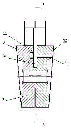
The invention relates to a pilot plant sluice valve. The pilot plant sluice valve is characterized by comprising a pair of valve seats, a flashboard, a valve rod and an auxiliary flashboard; a pressure releasing hole A communicating a flow channel liquid feeding side and the cavity of a valve body is formed in the liquid feeding side of the valve seats; an auxiliary flashboard accommodating groove is formed at the center of a T-shaped groove at the top of the flashboard, and a pressure releasing hole C is formed in a sealing face B of the liquid discharging side of the side of the auxiliary flashboard accommodating groove; the lower end of the valve rod can move for a certain distance in the T-shaped groove; the auxiliary flashboard is mounted at the lower end of the valve rod and is embedded into the auxiliary flashboard accommodating groove, and is provided with a sealing face C, a pressure releasing hole B and a pressure releasing hole D. The pilot plant sluice valve has the advantages that when the valve is opened and closed, the initial valve rod is utilized to drive the auxiliary flashboard to move so as to allow the pressure releasing holes A, B, C and D to form a pressure releasing channel, the pressures on the liquid feeding side and the liquid discharging side are balanced, the opening torque is reduced accordingly, wearing caused by sealing face friction increasing is avoided, and service life is prolonged.

Description

technical field [0001] The invention relates to a gate valve, in particular to a pilot type power station gate valve. Background technique [0002] High-temperature, high-pressure, large-diameter electric gate valves are mainly used in the main steam pipeline system and main water supply system of power plants to control the opening and closing of pipelines and realize the controllable operation of the unit. Its quality and reliability maintain the safety and efficiency of the unit, and it is the key valve equipment of the power plant. [0003] Generally, the opening and closing resistance of the gate valve is overcome by the mechanical device of the electric actuator. Due to the large pressure difference between the front and rear of the gate, the friction of the sealing surface increases, and the sealing surface is easy to wear. [0004] In addition, the larger the caliber and pressure of the gate valve, the sharper the opening and closing torque of the valve, and the req...

Claims


Application Information

Patent Timeline
Patent Type & Authority Patents(China)
IPC IPC(8): F16K3/02F16K3/314
CPCF16K3/02F16K3/0209F16K3/314
Inventor 孟庆银张建华
Owner NANTONG POWER STATION VALVE
Learn More