Centre vibrating and outputting mechanism for water meter

An output mechanism and top-notch technology, applied in the field of automatic output mechanism and water meter assembly structure, can solve the problems of poor assembly quality and assembly uniformity, low work efficiency, high labor intensity, etc., and achieve the effect of improving work efficiency and facilitating clamping

Active Publication Date: 2014-07-16
安徽格太信控科技有限公司
View PDF10 Cites 2 Cited by
  • Summary
  • Abstract
  • Description
  • Claims
  • Application Information

AI Technical Summary

Problems solved by technology

[0004] At present, the tip is usually manually pressed into the installation hole at the bottom of the impeller box. This installation method has the following disadvantages: firstly, it is difficult to grasp the magnitude of the pressure applied by hand, and it is difficult to control the depth of the tip; the direction of the pressure applied by hand is not accurate. , which may lead to deviations in the position of the top; therefore, the final assembly quality and assembly uniformity are poor. Secondly, it is inconvenient for workers to operate, labor-intensive, and easily injured; finally, due to the low degree of automation, the overall work efficiency Low, the work efficiency of skilled workers is difficult to break through the limit
Although this patent solves the automatic assembly process of the tip and the impeller box, the setting of the tip on the positioning mechanism before assembly still needs to be completed by manual operation, which is not fully automated and can be further improved

Method used


Image

  • Centre vibrating and outputting mechanism for water meter
  • Centre vibrating and outputting mechanism for water meter
  • Centre vibrating and outputting mechanism for water meter

Examples


Embodiment Construction

[0024] The present invention will be further described in detail below in conjunction with the accompanying drawings and embodiments.

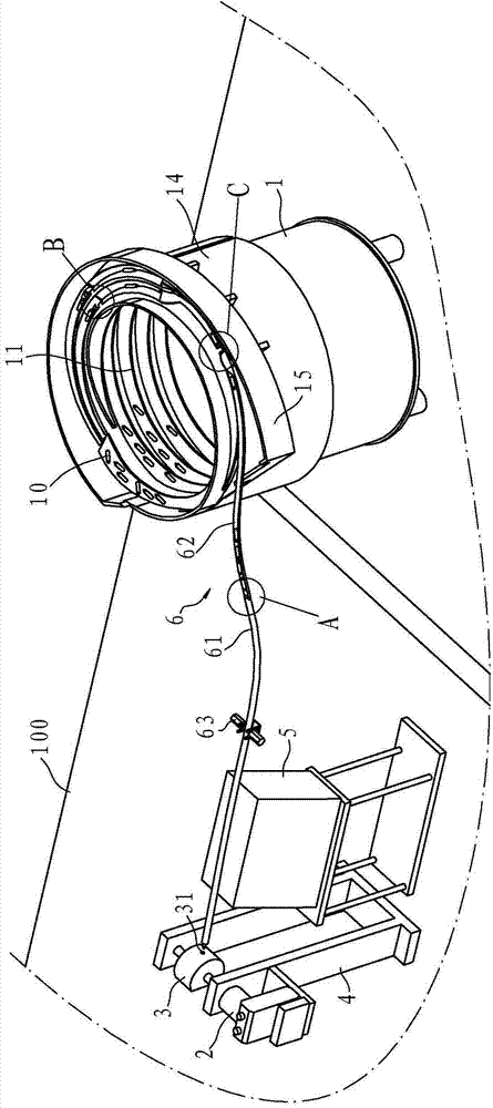
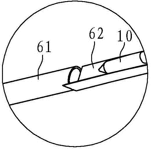
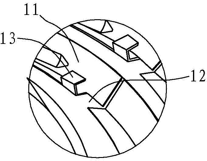
[0025] Such as figure 1 , figure 2 , image 3 and Figure 4 As shown, the top vibration output mechanism for water meters in this embodiment includes a worktable 100, a vibration plate 1, a swing cylinder 2, a blanking track 6, an oscillator 5 and a controller (not shown in the figure), and the worktable 100 There is a bracket 4 on it, and the upper end of the vibrating plate 1 has a cylindrical part 14. The inner wall of the cylindrical part 14 is formed with a guide rail 11 extending upward in a spiral shape. The guide rail 11 is formed with a plurality of notches 12, and the length of the notch 12 is less than The length of the top 10 is greater than half of the length of the top 10; the discharge port of the cylindrical part 14 has a side groove 15, and one end of the side groove 15 is connected with the guide rail 11, and the guide ra...


PUM


Abstract

The invention provides a centre vibrating and outputting mechanism for a water meter. The centre vibrating and outputting mechanism is characterized by comprising a vibrating plate, a swing air cylinder, an unloading rail and a vibrating device. The upper end of the vibrating plate is provided with a cylinder portion. A guide rail extending upwards in a spiral mode is formed on the inner wall of the cylinder portion. A notch is formed in the guide rail. The length of the notch is smaller than the length of a centre. The power output end of the swing air cylinder is provided with a swing block. An internally-arranged groove for the single centre to be arranged is formed in the swing block. The upper end of the unloading rail is connected with an output opening of the guide rail. The lower end of the unloading rail is arranged close to the swing block. The vibrating device is arranged on the lower end face of the unloading rail. When the vibrating plate works, the centre with the forward tip can cross the notch and move forward continuously, while the centre with the backward tip falls from the notch due to the gravity. Compared with the prior art, the centre vibrating and outputting mechanism has the advantages of being high in centre output efficiency and low in failure rate.

Description

technical field [0001] The invention relates to a water meter assembly structure, in particular to an automatic output mechanism for a tip used in a water meter, and belongs to the technical field of water meter processing and assembly. Background technique [0002] The rotor-type water meter is a kind of speed-type water meter, which is widely used in the world. The metering mechanism of the rotor-type water meter is mainly composed of a gear box, an impeller box (leaf joint), an integral impeller, a top, an adjusting plate, etc., among which the gear box and the impeller box form the movement. The metering mechanism plays a key role in the metering performance and durability of the water meter. [0003] Patent No. ZL200710035843.5 Chinese Invention Patent "A Rotary Wing Water Meter" (authorized announcement No. CN100529681C) China discloses a water meter, its structure: the tip is installed at the center of the bottom of the impeller box, at the bottom of the impeller sha...

Claims


Application Information

Patent Timeline
Patent Type & Authority Applications(China)
IPC IPC(8): G01F15/00
Inventor 赵如松敖开才
Owner 安徽格太信控科技有限公司
Why Eureka
Try Eureka