
Method for testing capacitive current of isolated neutral system

A technology with ungrounded neutral point and system capacitance. It is used in current/voltage measurement, resistance/reactance/impedance measurement, measurement devices, etc., which can solve the problem of insecurity of personnel and equipment, increase of operating procedures, and deviation of test results. major problems, to achieve the effect of improving test efficiency, accurate test results, and reducing power outage time

Active Publication Date: 2014-07-16
STATE GRID JIANGXI ELECTRIC POWER CO LTD RES INST +1
View PDF8 Cites 11 Cited by
  • Summary
  • Abstract
  • Description
  • Claims
  • Application Information

AI Technical Summary

Benefits of technology

This technology helps reduce stress on electronic devices caused when they fail due to sudden or temporary power loss while still being able to perform tests accurately with one phase voltages instead of multiple phases. It also improves safety measures against potential damage from high levels of noise generated by other equipment within the same area without affecting their performance.

Problems solved by technology

There has been increasing concern about potential damage due to arcing between two parts of electricity transmission systems during times of high demand without interrupting their power supplies. Current techniques such as measuring inductive (L) currents have limitations because they require extra devices on both sides of the circuitry being tested. Directly attaching an electrode called an AC contactor can provide precise measurements while minimizing any risks associated with these new technologies. However, this approach requires careful handling and monitoring of voltages across all components connected through wires, making it difficult if practical. Interference compensation circuits may improve accuracy compared to other approaches like zero crossing detection.

Method used


Image

  • Method for testing capacitive current of isolated neutral system
  • Method for testing capacitive current of isolated neutral system

Examples


Embodiment Construction

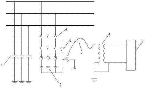
[0013] The specific implementation of the capacitor current test using the neutral point of the capacitor bank is as follows:

[0014] (1) Check the wiring mode and operation mode of the ungrounded system. All lines of the system should be put into operation, and record the outgoing line of the system and the actual operation.

[0015] (2) If the arc suppression coil has been configured on site, record the capacitive current, inductance current, gear position, detuning degree and residual current recorded by the arc suppression coil control device. According to the wiring mode and operation mode, exit all arc suppression coils that have electrical connection with the system under test and record the exit of arc suppression coils.

[0016] (3) The external single-phase PT is placed on the insulating pad, and the high-voltage tail, the low-voltage tail and the outer casing are grounded at one point.

[0017] (4) Connect the output end of the capacitance current tester to the si...


PUM


Abstract

The invention discloses a method for testing a capacitive current of an isolated neutral system, and belongs to the technical field of high-voltage testing. The method includes the steps that different-frequency signals are injected from the neutral point of a capacitor bank (2) by a single-phase electromagnetic voltage transformer (6) through an insulated cable (5), and the capacitive current of the isolated neutral system is obtained through calculation. The method can be carried out in an electrification mode, the problem that an original capacitive current test is low in testing efficiency, inaccurate in testing result, unsafe in testing method and the like is solved, and the testing method provides a basis for accurately measuring the capacitive current of the isolated neutral system and allocating an arc suppression coil according to the testing result or checking the capacity of the arc suppression coil.

Description


Claims


Application Information

Patent Timeline
Owner STATE GRID JIANGXI ELECTRIC POWER CO LTD RES INST
Learn More