
Knob test device and knob test equipment

A technology of test device and rotary drive device, which is applied in the direction of measuring device, circuit breaker test, mechanical component test, etc., can solve the problems of complicated test process, cycle and cost increase, etc., so as to reduce test cost and simplify test procedure Effect

Active Publication Date: 2016-08-17
SAIC VOLKSWAGEN AUTOMOTIVE CO LTD
View PDF7 Cites 0 Cited by
  • Summary
  • Abstract
  • Description
  • Claims
  • Application Information

AI Technical Summary

Problems solved by technology

In the existing test technology, the linear press test and the rotation test cannot be performed together on one device, and different devices need to be used.
This complicates the test process, and requires multiple disassembly and assembly of the knob to be tested and connection with the test equipment, which forces the test cycle and cost to increase

Method used


Image

  • Knob test device and knob test equipment
  • Knob test device and knob test equipment
  • Knob test device and knob test equipment

Examples


Embodiment Construction

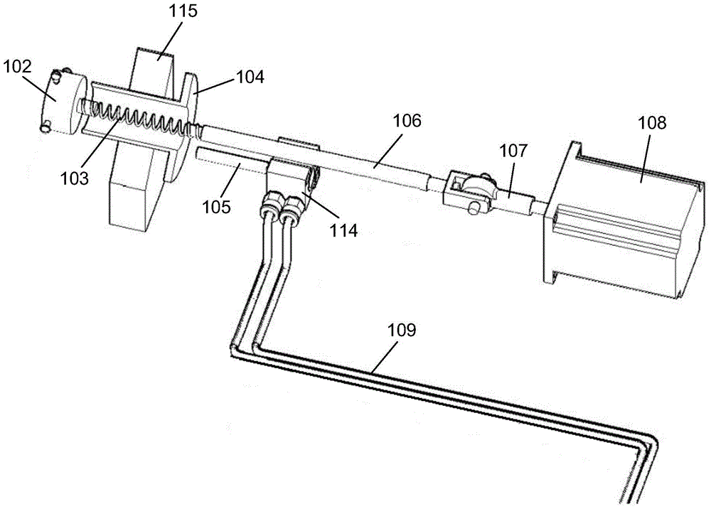
[0023] refer to figure 1 as shown, figure 1 A structural diagram of a knob testing device according to an embodiment of the present invention is disclosed. The knob test device includes: a fixture, an elastic shaft, a linear testing mechanism and a rotating testing mechanism.

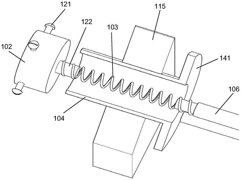
[0024] The clamp 102 is fixed on the knob. further reference figure 2 As shown, the clamp 102 is cylindrical, the first end is open, and the second end is closed. The knob is put into the clamp by the first end of the clamp. The side wall of the clamp 102 has a fixing bolt 121. The fixing bolt 121 is tightened to tighten the clamp 102. fixed on the knob. In the illustrated embodiment, there are four fixing bolts 121 on the side wall of the clamp 102 , and the four fixing bolts are tightened inwardly to clamp the knob, so that the knob and the clamp 102 are firmly connected. The second end of the clamp has a protrusion 122 connected to the first end of the elastic shaft.

[0025] The elastic shaft...


PUM


Abstract

The invention discloses a knob test device which is characterized by comprising a clamp, an elastic shaft, a linear test mechanism and a rotating test mechanism. The clamp is fixed to a knob, and the first end of the elastic shaft is connected to the clamp. The linear test mechanism comprises a linear driving device and a linear transmission device. The linear transmission device is installed on the elastic shaft, and the linear driving device exerts drive force to drive the linear transmission device to move along a straight line, overcomes the elastic force of the elastic shaft and makes contact with the clamp. The knob is pressed through the clamp, so that the linear driving device withdraws the driving force, and the linear transmission device is reset under the elastic force of the elastic shaft and is separated from the clamp. The rotating test mechanism comprises a rotating driving device and a rotating transmission device. The rotating transmission device is connected between the second end of the elastic shaft and the rotating driving device, the rotating driving device drives the rotating transmission device to rotate, and the knob is driven to rotate through the elastic shaft and the clamp.

Description

technical field [0001] The invention relates to the testing technology of auto parts, more specifically, relates to the testing device of the knob in the center console part of the car. Background technique [0002] Car center console components are an important part of human-vehicle interaction, which directly affects the experience of using the vehicle. At present, the application of the integrated knob is more and more extensive, and it has many applications in the multimedia player of the center console, air conditioning control, etc. The integrated knob means that the knob has two functions: overall rotation and overall pressing, that is, the knob can be rotated and pressed, and the rotation and pressing correspond to different operations. [0003] The frequency of use of the integrated knob is very high, so its durability is an important part of the quality of the integrated knob. Because the integrated knob has two working modes: pressing and rotating, both working ...

Claims


Application Information

Patent Timeline
Patent Type & Authority Patents(China)
IPC IPC(8): G01R31/327G01M13/00
Inventor 张毅陈维阳徐旭昱叶晓倩
Owner SAIC VOLKSWAGEN AUTOMOTIVE CO LTD
Learn More