Testing method of a unit to be tested

A test method and test board technology, applied in electronic circuit testing and other directions, can solve problems such as cumbersome procedures, inability to integrate data, and time-consuming

Active Publication Date: 2012-05-30
蚌埠市科达电器有限公司
View PDF7 Cites 5 Cited by
  • Summary
  • Abstract
  • Description
  • Claims
  • Application Information

AI Technical Summary

Problems solved by technology

[0009] To sum up the above, the existing empty board test method requires various tests to be performed in sections, and the data collected in each test cannot be integrated. For the tester, the multi-se

Method used


Image

  • Testing method of a unit to be tested
  • Testing method of a unit to be tested
  • Testing method of a unit to be tested

Examples


Embodiment Construction

[0037] The implementation of the present invention is described below through specific specific examples. Those skilled in the art can easily understand other advantages and effects of the present invention from the content disclosed in this specification.

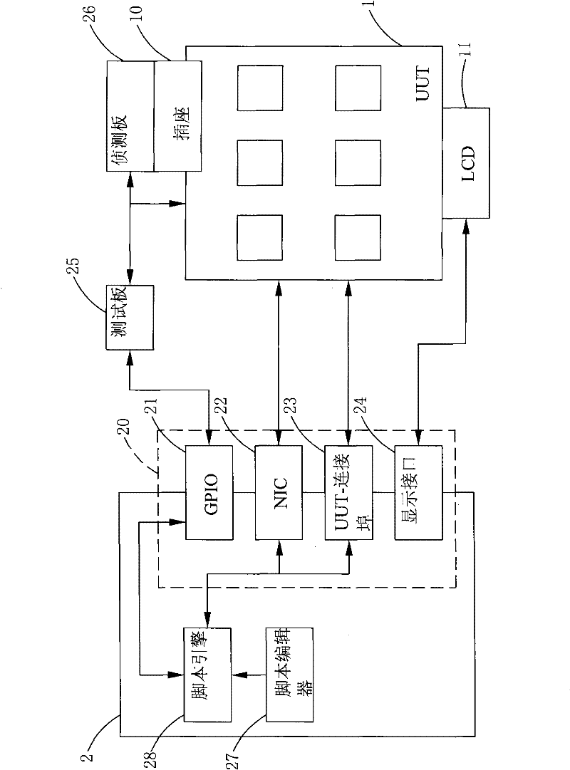
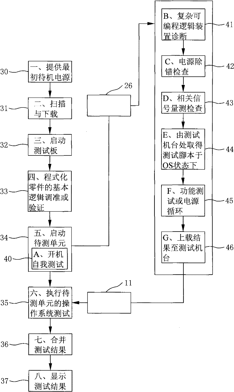
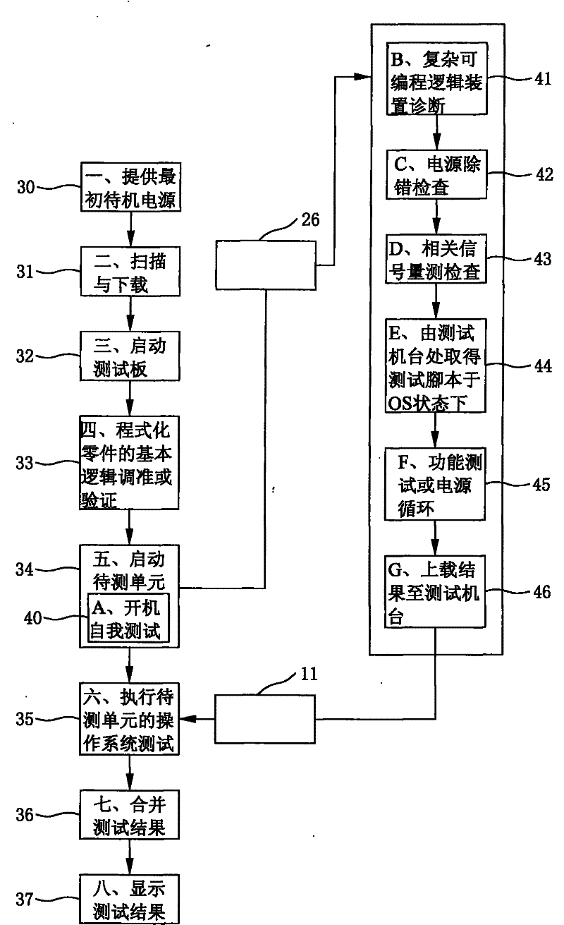
[0038] see figure 1 and figure 2 Shown, the present invention is a kind of testing method of unit to be tested, and its step comprises:

[0039] 1. Provide initial standby power 30 : provide a standby power to at least one unit under test 1 , and its connection method is described in detail as follows.

[0040] At least one unit to be tested 1 is electrically connected to a test machine 2, the unit to be tested 1 can be a main board or a circuit substrate, and the test machine 2 can be a console computer or a production test system (ITCnD CLI, ITCnD Command Line Interface), the test machine 2 has a connection interface 20, and the connection interface 20 has an input and output interface 21 (General Purpose Input Output...


PUM


Abstract

The invention provides a testing method of a unit to be tested, comprising the following step of electrically connecting the unit to be tested to a testing machine platform, wherein the testing machine platform produces a test script and executes the test script so as to perform non-operation system test and operation system test to the unit to be tested, and the test results can be combined so as to simplify testing procedures, shorten the testing time and improve the accuracy of the test.

Description

technical field [0001] The present invention is a testing method for a unit to be tested, which provides a method for measuring the unit to be tested, such as a circuit board or a main board in an empty state, and its non-operating system test and operating system test, and can combine the two test results , thereby saving test time, simplifying test procedures and improving test accuracy. Background technique [0002] The motherboard is the main executive component in the computer. It is electrically connected to various electronic components, such as hard disks, ports, power supplies, etc. Therefore, if the computer lacks the motherboard, the computer cannot operate. [0003] The motherboard will use the basic input and input system (Basic Input) stored in the flash memory (Flash memory) or electronically erasable programmable read-only memory (Electrically-Erasable Programmable Read-Only Memory, hereinafter referred to as EEPRM) before starting up. / Output System, herein...

Claims


Application Information

Patent Timeline
IPC IPC(8): G01R31/28
Inventor 金志仁陈琏锋
Owner 蚌埠市科达电器有限公司
Why Eureka
Try Eureka