Method and apparatus for testing tunnel magnetoresistive effect element

a tunnel magnetoresistive and element technology, applied in the field of tunnel magnetoresistive effect element testing, can solve the problems of not being generated, adversely affecting the bias magnetic field of the mr head element, and it is difficult to detect the burst noise rtn with reliability, so as to achieve the effect of extremely easy confirmation of stability and reliability of the tmr elemen

Active Publication Date: 2007-06-26
TDK CORPARATION
View PDF5 Cites 6 Cited by
  • Summary
  • Abstract
  • Description
  • Claims
  • Application Information

AI Technical Summary

Benefits of technology

[0012]It is therefore an object of the present invention to provide a method and apparatus for testing a TMR element, whereby stability and reliability of the TMR element can be extremely easily confirmed without destroying the element.
[0014]With respect to a plurality of TMR elements, if a current is fed from a anti-substrate side (upper side) to a substrate side (lower side), a distribution of degrees of change in their resistances determined based upon the first resistance value (initial resistance value) and the second resistance value (resistance value just after continuously feeding the current through the TMR element from the anti-substrate side to the substrate side for a predetermined time period), that is a distribution of rates of change in resistance values or changed amount of resistance values, polarizes two groups. The first group is a set of the TMR elements with rates of change in resistance values or changed amount of resistance values smaller than 1, whereas the second group is a set of the TMR elements with rates of change in resistance values or changed amount of resistance values equal to or larger than 1. Many of the TMR elements in the second group generate RTN, whereas few of the TMR elements in the first group generate RTN. Also, breakdown voltages of the TMR elements in the first group are higher than those of the TMR elements in the second group. Therefore, it is possible to extremely easily evaluate non-defective / defective with respect to a TMR element by confirming stability and reliability of the TMR element depending upon whether the second resistance that is the resistance value just after continuously feeding a current through the TMR element for a predetermined time period is smaller than the first or initial resistance value. Moreover, because this evaluation test can be performed without destroying the TMR element, 100% inspection of the manufactured TMR elements becomes possible. Particularly, according to the present invention, because evaluation test of non-defective and defective products can be performed only by judging whether the resistance after the passage of current is smaller than the initial resistance or not irrespective of the period for feeding the current to the TMR head element, the voltage applied to the TMR head element and the material for the TMR head element, the evaluation test procedure can become extremely simple.
[0020]As aforementioned, with respect to a plurality of TMR elements, if a current is fed from a anti-substrate side (upper side) to a substrate side (lower side), a distribution of degrees of change in their resistances determined based upon the first resistance value (initial resistance value) and the second resistance value (resistance value just after continuously feeding the current through the TMR element from the anti-substrate side to the substrate side for a predetermined time period), that is a distribution of rates of change in resistance values or changed amount of resistance values, polarizes two groups. The first group is a set of the TMR elements with rates of change in resistance values or changed amount of resistance values smaller than 1, whereas the second group is a set of the TMR elements with rates of change in resistance values or changed amount of resistance values equal to or larger than 1. Many of the TMR elements in the second group generate RTN, whereas few of the TMR elements in the first group generate RTN. Also, breakdown voltages of the TMR elements in the first group are higher than those of the TMR elements in the second group. Therefore, it is possible to extremely easily evaluate non-defective / defective with respect to a TMR element by confirming stability and reliability of the TMR element depending upon whether the second resistance that is the resistance value just after continuously feeding a current through the TMR element for a predetermined time period is smaller than the first or initial resistance value. Moreover, because this evaluation test can be performed without destroying the TMR element, 100% inspection of the manufactured TMR elements becomes possible. Particularly, according to the present invention, because evaluation test of non-defective and defective products can be performed only by judging whether the resistance after the passage of current is smaller than the initial resistance or not irrespective of the period for feeding the current to the TMR head element, the voltage applied to the TMR head element and the material for the TMR head element, the evaluation test procedure can become extremely simple.

Problems solved by technology

However, because the RTN is a burst noise, it may not be generated during the predetermined period of time.
However, this testing method not only additionally needs a magnetic field generation device for applying the external DC magnetic field to the MR head element but also adversely affects a bias magnetic field of the MR head element due to the application of the external magnetic field.
On top of that, it is difficult to detect the burst noise RTN with reliability even by this testing method.
As will be noted, the conventional reliability test of measuring a breakdown voltage of the magnetic head cannot be performed for all the magnetic heads because it breaks the magnetic head during the breakdown voltage measurement.
However, according to this testing method and apparatus, because it is necessary to determine the threshold value of the resistance-changing ratio each time the period for feeding the current, the voltage applied to the TMR element and the material for the TMR element change, the testing procedure becomes very complicated.
Therefore, it is very difficult to evaluate whether each TMR element is a non-defective product or not.

Method used


Image

  • Method and apparatus for testing tunnel magnetoresistive effect element
  • Method and apparatus for testing tunnel magnetoresistive effect element
  • Method and apparatus for testing tunnel magnetoresistive effect element

Examples


Embodiment Construction

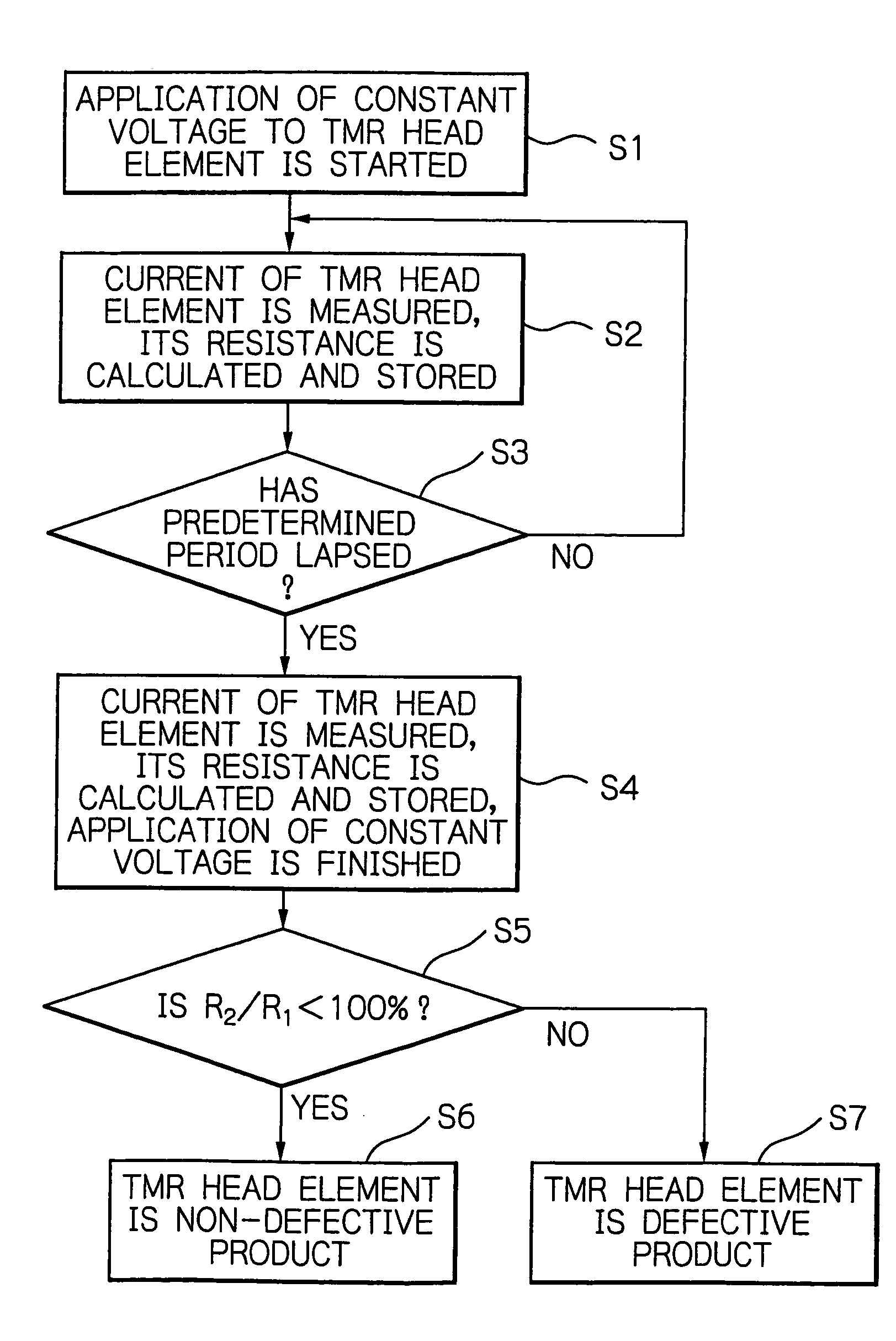
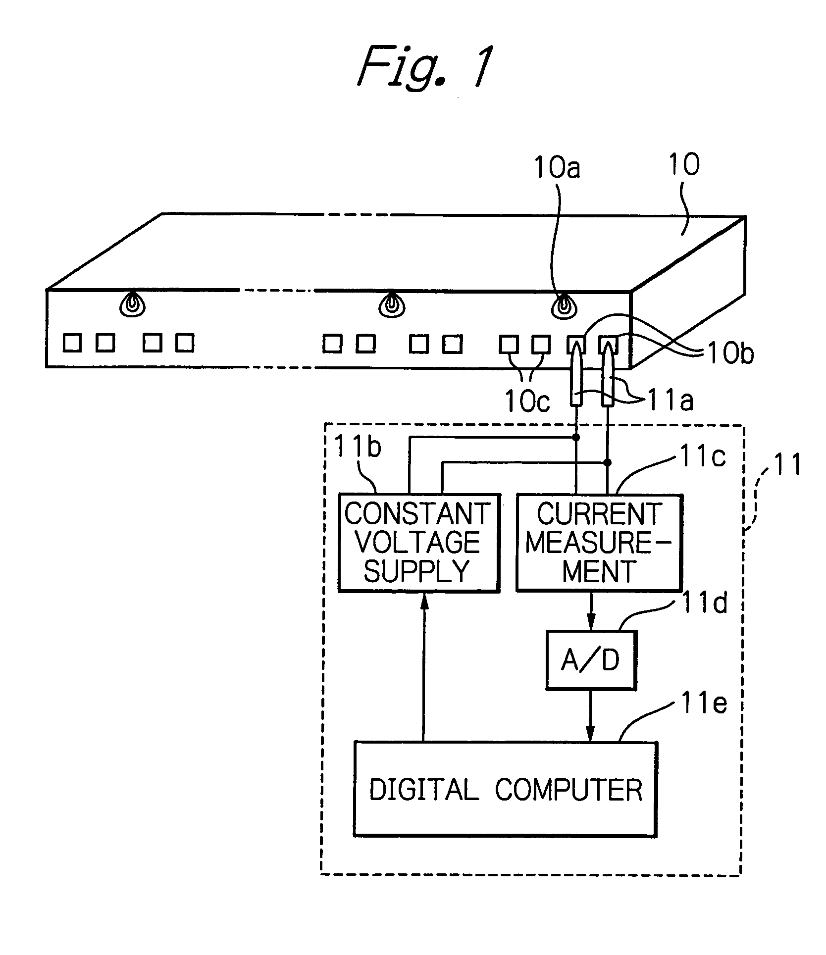
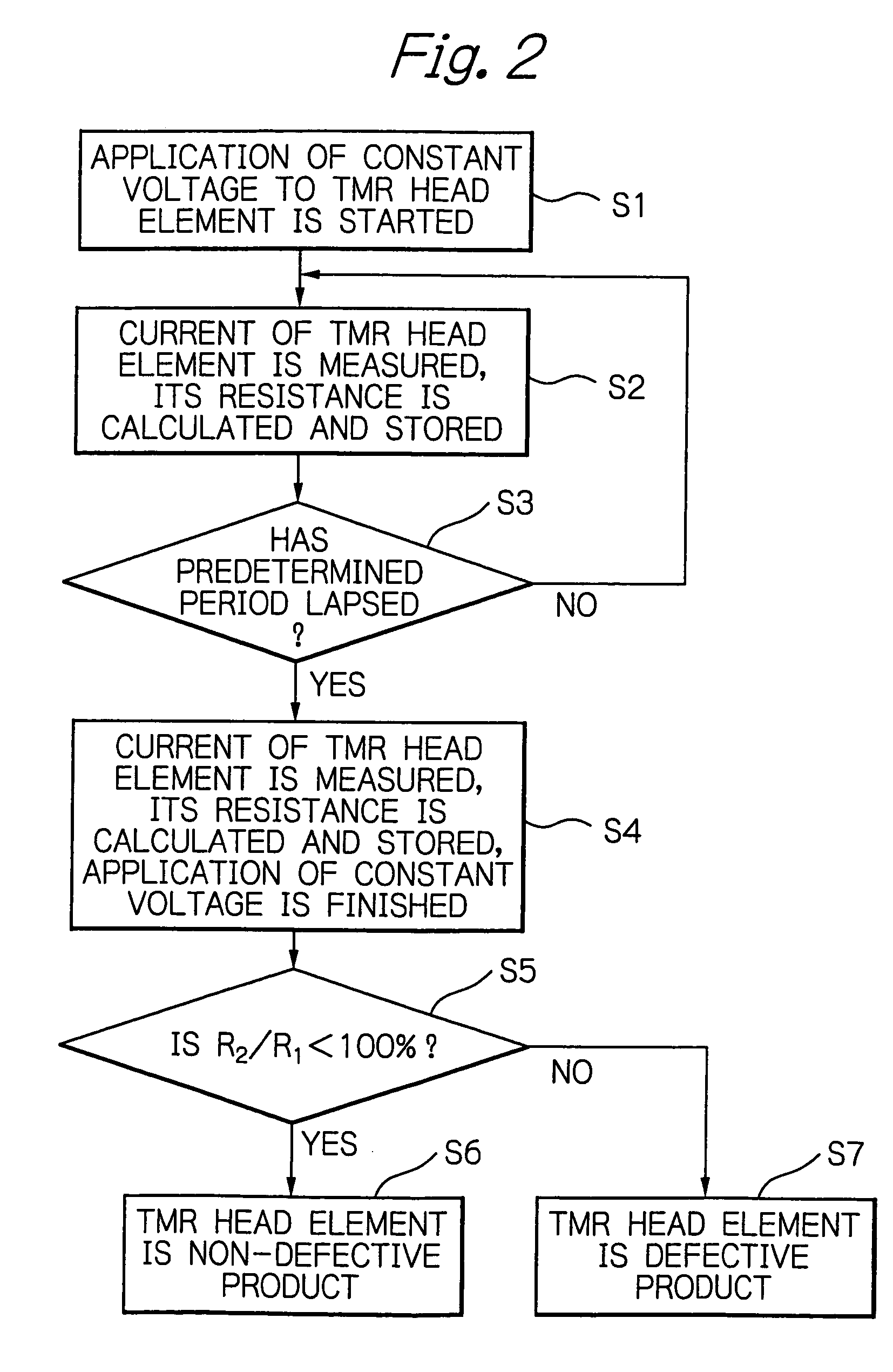
[0036]FIG. 1 schematically illustrates a configuration of testing a TMR head element as a preferred embodiment according to the present invention.

[0037]In the figure, reference numeral 10 denotes a bar member or bar block with a plurality of aligned TMR heads that are not individually separated yet, and 11 denotes a testing apparatus of the TMR head element.

[0038]The bar member 10 is provided by forming a large number of TMR heads arranged in matrix on a wafer according to thin-film technology, by cutting the wafer into bar shaped members so that each member has the aligned magnetic heads, and by lapping the ABS of the head member 10 so as to adjust gap-depth (MR height) of the heads. Each TMR head 10a of the bar member 10 is provided with a TMR read head element, an inductive write head element, a pair of terminal pads 10b electrically connected to the TMR read head element, and a pair of terminal pads 10c electrically connected to the inductive write head element.

[0039]The testing...


PUM

PropertyMeasurementUnit
constant voltageaaaaaaaaaa
timeaaaaaaaaaa
breakdown voltageaaaaaaaaaa

Abstract

Testing a TMR element includes a step of measuring initially a resistance value of the TMR element to provide the measured resistance value as a first resistance value, a step of measuring a resistance value of the TMR element after continuously feeding a current through the TMR element from a anti-substrate side to a substrate side for a predetermined period of time, to provide the measured resistance value as a second resistance value, and a step of evaluating the TMR element by comparing the first resistance value and the second resistance value with each other.

Description

PRIORITY CLAIM[0001]This application claims priority from Japanese patent application No. 2004-128111, filed on Apr. 23, 2004, which is incorporated herein by reference.BACKGROUND OF THE INVENTION[0002]1. Field of the Invention[0003]The present invention relates to a method and apparatus for testing a tunnel magnetoresistive effect (TMR) element such as a TMR head element using the tunnel magnetoresistive effect or a magnetoresistive random access memory (MRAM).[0004]2. Description of the Related Art[0005]An evaluation test is in general performed for determining whether or not a thin-film magnetic head with a magnetoresistive effect (MR) head element is a non-defective product, during or after manufacturing the magnetic head. This evaluation test includes a stability test for confirming that any random telegraph noise (RTN) such as Barkhausen noise (BHN) is not produced from the MR head element, and a reliability test for confirming that a breakdown voltage of the MR head element i...

Claims


Application Information

Patent Timeline
Patent Type & Authority Patents(United States)
IPC IPC(8): G11B5/455G11B5/39G01R33/09G11C11/00G11C29/50H01L21/8246H01L27/105H01L43/08H01L43/12
CPCG11C11/16G11C29/50G11C29/50008G11C2029/5006
Inventor SARUKI, SHUNJIINAGE, KENJIHACHISUKA, NOZOMUKIYONO, HIROSHI
Owner TDK CORPARATION
Why Eureka
Try Eureka