Supercharge Your Innovation With Domain-Expert AI Agents!

Method and apparatus for liquid level loop control

A loop control and liquid level technology, applied in the field of control systems, can solve problems such as blockage, liquid ingress, and rupture

Active Publication Date: 2017-03-22
FISHER CONTROLS INT LLC
View PDF6 Cites 0 Cited by
  • Summary
  • Abstract
  • Description
  • Claims
  • Application Information

AI Technical Summary

Problems solved by technology

If the liquid level exceeds the high threshold level, the liquid may enter the natural gas pipeline and cause blockage and / or rupture in the pipeline

Method used


Image

  • Method and apparatus for liquid level loop control
  • Method and apparatus for liquid level loop control
  • Method and apparatus for liquid level loop control

Examples


Embodiment Construction

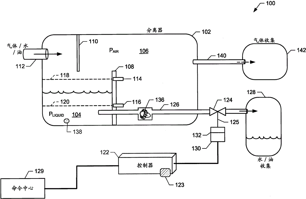
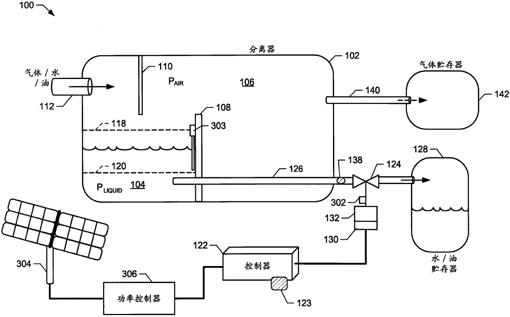
[0012] While the following describes exemplary methods and apparatus that include, among other components, software and / or firmware executed on hardware, it should be noted that this system is exemplary only and should not be viewed as limiting. For example, it is contemplated that any or all of these hardware, software, and firmware components may be implemented exclusively in hardware, exclusively in software, or in a combination of hardware and software. Thus, although the exemplary methods and apparatus described below in connection with a natural gas well site, the exemplary methods and apparatus may be used in any application to separate gases from liquids.

[0013] Natural gas well sites extract unrefined natural gas from underground natural reserves. Natural gas extracted from the ground is in a fluid mixture of liquids, slurries and gases. One of the first steps is to purify the natural gas to separate any liquids, slurry and / or water vapor from the gas so that the e...


PUM


Abstract

Exemplary methods and apparatus for liquid level loop control are disclosed. The disclosed exemplary method includes determining a first pressure of liquid in a tank via a sensor, measuring a second pressure of liquid in the tank via a turbine flowmeter, determining whether the first pressure is within a specified range from the second pressure within the deviation to determine an operating state of the turbine flow meter and to transmit a diagnostic message indicating that the turbine flow meter needs to be serviced based on the state of the turbine flow meter.

Description

technical field [0001] The disclosure herein relates generally to control systems and more particularly to methods and apparatus for level loop control. Background technique [0002] Natural gas well sites (eg, non-associated well sites) typically include separators to separate natural gas from liquids. These liquids may include, for example, water, oil and mud. The separator makes it possible to separate the produced natural gas from the liquid and / or water vapor by allowing the liquid and / or water vapor and the gas to be collected into corresponding collection chambers inside the separator. The liquid in the liquid collection chamber is sent to the liquid storage tank to separate the oil from the mud and water later. The gas in the gas collection tank is usually transported to the natural gas processing station or to the natural gas collection tank. [0003] The liquid level in the liquid collection tank of the separator must generally be maintained between a low thresh...

Claims


Application Information

Patent Timeline
Patent Type & Authority Patents(China)
IPC IPC(8): G01F25/00G01D9/12
CPCY10T137/0324Y10T137/7287G01F25/10G01F25/00
Inventor T·佩塞克B·伯莱奇
Owner FISHER CONTROLS INT LLC
Features
  • R&D
  • Intellectual Property
  • Life Sciences
  • Materials
  • Tech Scout
  • Unparalleled Data Quality
  • Higher Quality Content
  • 60% Fewer Hallucinations
Learn More