A vacuum annealing furnace

A vacuum annealing furnace and furnace technology, applied in the field of vacuum annealing furnace, can solve the problems that the temperature of the workpiece may only be about 500°C, the holding time, temperature difference, and heat treatment effect are different, etc., and achieve good annealing quality of the workpiece, heating transmission Heats up quickly and shortens the heating time

Active Publication Date: 2016-05-18
NICORE ELECTRICAL MFR CO LTD
View PDF8 Cites 0 Cited by
  • Summary
  • Abstract
  • Description
  • Claims
  • Application Information

AI Technical Summary

Problems solved by technology

These two forms of heat transfer are both heating methods that gradually transfer heat from the periphery of the workpiece to the center. When the furnace is made larger in order to increase production, the heat transfer distance is also longer, such as: the inner cavity of the furnace When the diameter is larger than φ900mm, the heat transfer distance is more than 400mm. If the heat treatment temperature of the workpiece is 800°C, that is, when the temperature of the workpiece around the outside reaches 800°C, the temperature of the central workpiece may only be about 500°C. When the temperature of the central workpiece rises slowly When the temperature reaches 800°C, the temperature of the outer and surrounding workpieces has been kept at 800°C for more than two hours, so the holding time and temperature difference between the peripheral workpieces and the central workpiece at 800°C are quite different, resulting in the actual heat treatment effect of each workpiece. Different
However, in practical applications, it is always required that the heat treatment effect of each workpiece in the same furnace is consistent, and the existing vacuum annealing furnace is difficult to achieve this effect

Method used


Image

  • A vacuum annealing furnace
  • A vacuum annealing furnace
  • A vacuum annealing furnace

Examples


Embodiment Construction

[0012] The present invention is described in further detail by the following examples.

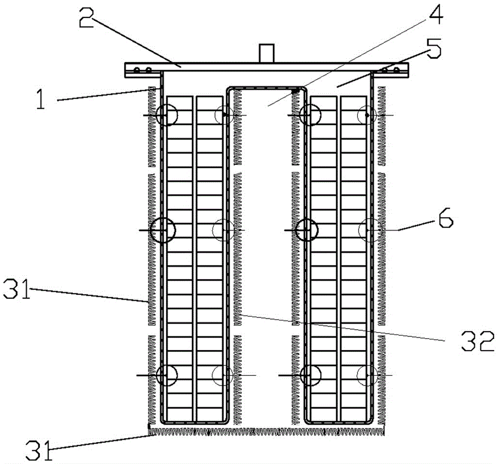
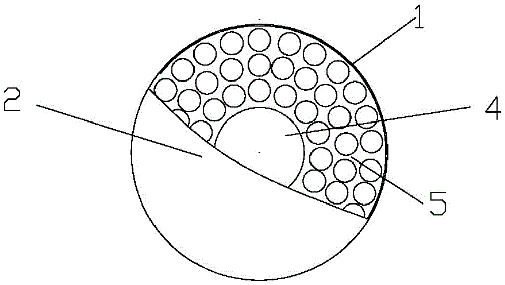
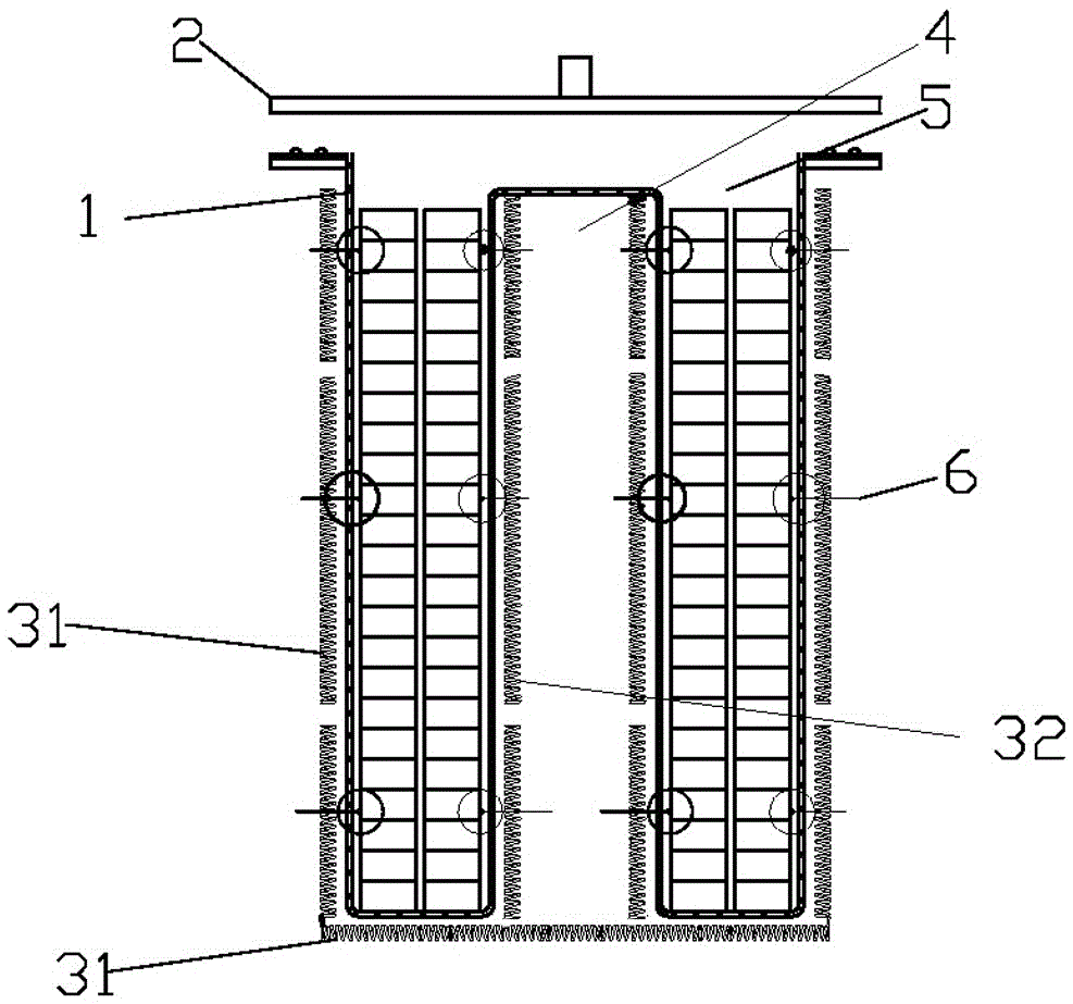
[0013] like Figure 1-3 As shown, a vacuum annealing furnace is composed of a furnace chamber 1, a furnace cover 2, a first heating element 31 and its temperature regulating device, a second heating element 32 and its temperature regulating device, and a barrel-shaped inner chamber 4. A sealing ring is provided between the furnace cover 2 and the furnace 1 to form a vacuum inner cavity in the furnace, and its vacuum degree can reach 1-0.001pa. The first heating element 31 is installed on the outer wall or inner wall of the furnace 1 and the outside of the bottom of the furnace 1. The furnace 1 is a barrel-shaped structure with an upward opening. , the opening of the barrel-shaped liner 4 is connected with a circular arc transition between the bottom middle of the furnace 1 to form an annular discharge area 5, and the inner cavity of the barrel-shaped liner 4 is fixedly installed with a se...


PUM


Abstract

The invention discloses a vacuum annealing furnace. The vacuum annealing furnace comprises a furnace liner and a furnace cover, wherein a sealing ring is arranged between the furnace cover and the furnace liner to form a vacuum inner cavity; a first heating component is installed on the outer wall or the inner wall and the bottom outer side of the furnace liner; the furnace liner is of a bucket-shaped structure with an upward opening; a bucket-shaped liner with a downward opening is arranged at the middle part of the furnace liner; the opening part of the bucket-shaped liner is connected with the bottom middle part of the furnace liner by arc transition to form an annular discharge area; and a second heating component and a temperature adjustment device are installed in the inner cavity of the bucket-shaped liner. The vacuum annealing furnace is capable of heating an annealing workpiece from the peripheral area of the workpeice and the middle area of the workpeice simultaneously to realize bidirectional heat transfer, thus greatly reducing the heat transfer distance between the annealing workpieces; and each workpiece is uniform in overall heating, thus improving the quality of the whole annealing workpieces.

Description

technical field [0001] The invention relates to the technical field of metal material annealing equipment, in particular to a vacuum annealing furnace. Background technique [0002] Vacuum heat treatment refers to the heat treatment process in which the workpiece is heated, kept warm or cooled in a vacuum state. Vacuum heat treatment can realize almost all heat treatment processes involved in conventional heat treatment, but the quality of heat treatment is greatly improved. Compared with conventional heat treatment, vacuum heat treatment can achieve no oxidation, no decarburization, no carburization at the same time, so as to achieve the effect of bright and clean workpiece surface. [0003] The traditional vacuum annealing furnaces used for heat treatment of metal materials include internal heating type and external heating type. The so-called internal heating type means that the heating element is installed on the inner wall of the furnace to directly heat the workpiece;...

Claims


Application Information

Patent Timeline
Patent Type & Authority Patents(China)
IPC IPC(8): C21D1/773C21D1/26
Inventor 张希望
Owner NICORE ELECTRICAL MFR CO LTD
Why Eureka
Try Eureka