Overall sliding construction method for large-span special-shaped space grid pipe truss

A space grid and overall sliding technology, which is applied in the direction of construction, building structure, and building material processing, can solve the problems of low construction efficiency, time-consuming and laborious, etc., and achieve the effect of uniform force and not easy to deform

Inactive Publication Date: 2014-07-23
SHANGHAI ERSHIYE CONSTR CO LTD
5 Cites 13 Cited by

AI-Extracted Technical Summary

Problems solved by technology

The current steel structure slippage mostly adopts the method of accumulativ...

Method used

Described large-span special-shaped space grid pipe truss integral slippage construction method; In the pusher 13 on four tracks 3, one of them pusher on any one track in two tracks 31,32 of inner side Set as the master point, any one of the pushers in the other track is set as the follower point, and the pushers on the other two outer tracks 33 and 34 and the other pushers on the inner two tracks are set as the following points to be controlled by the synchronous controller. In this way, in the process of slipping, the linear velocity of each slip point is always consistent, so the slipping speed of the thruster at the master point is set as a standard value, which is used as the benchmark of speed and displacement in the synchronous control strategy. Under the control of the computer, the slave point tracks and compares the master point with displacement and linear velocity, and performs dynamic adjustments to ensure that each pusher is always synchronized during the sliding process. An...

Abstract

The invention relates to the field of steel structure monolithic architecture construction, in particular to an overall sliding construction method for a large-span special-shaped space grid pipe truss. The method is characterized by comprising the following steps that 1, a truss erecting field is determined; 2, a trestle type Bailey frame is erected in a foundation trench, and a concrete strip foundation is laid outside the foundation trench; 3, four parallel rails are laid; 4, spliced supporting frames and sliding supporting frames are arranged; 5, the truss is erected through a hoist; 6, vertical and horizontal unloading operating is carried out on the erected truss; 7, the sliding supporting frames are connected with ejectors; 8, synchronous control devices are arranged between the ejectors; 9, the ejectors are started, and the sliding supporting frames are made to synchronously slide to the target position; 10, the sliding supporting frames are dismounted, and a truss support is mounted. Through the steps, the large-span special-shaped space grid pipe truss can be mounted in a sliding mode, the truss is stressed evenly in the sliding mounting process, and deformation is not prone to being caused.

Application Domain

Technology Topic

Image

  • Overall sliding construction method for large-span special-shaped space grid pipe truss
  • Overall sliding construction method for large-span special-shaped space grid pipe truss
  • Overall sliding construction method for large-span special-shaped space grid pipe truss

Examples

  • Experimental program(1)

Example Embodiment

[0025] The present invention is further illustrated by specific examples below.
[0026] A large-span special-shaped space grid tube truss integral sliding construction method is characterized in that: it comprises the following steps;
[0027] Step 1. Determine the truss construction site according to the design drawings;
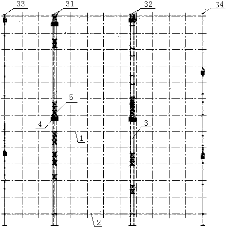
[0028] like figure 1 shown,
[0029] Step 2. Set up a trestle-type beret 1 in the building foundation pit, and lay a concrete strip foundation 2 outside the foundation pit;
[0030] Step 3. Lay four parallel tracks 3 on the trestle-type beret 1 and the concrete strip foundation 2;
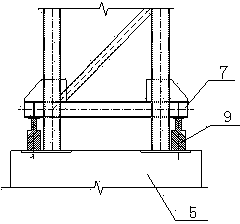
[0031] Step 4. According to the structural calculation and design height requirements, set the assembled support frame 5 and the sliding support frame 4 on the four parallel tracks 3;
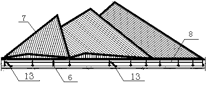
[0032] like figure 2 shown,
[0033] Step 5. Use a crane to build the truss 7 based on the sliding support frame 4 and the assembled support frame 5, wherein the assembled support frame 5 is located at the fulcrum of the truss 7, and the sliding support frame 4 is located at the lower part of the assembled support frame; 5
[0034] Step 6. Perform vertical and horizontal unloading operations on the constructed truss 7;
[0035] Step 7, connect each sliding support frame 4 with the ejector 13, and the ejector 13 is arranged on the track 3;
[0036] Step 8. A synchronous control device is set between each pusher 13;
[0037] Step 9, start the ejector 13, realize the synchronous action of the ejector 13 under the control of the synchronous control device, and make the sliding support frame 4 synchronously slide to the target position;
[0038] Step 10, disassemble the sliding support frame 4 and carry out the in-position, unloading and installation operations of the truss 7 support; wherein, the vertical unloading of the truss 7 support in place is carried out by the following methods:
[0039] like image 3 shown,
[0040] Step 1: Jack the 9-liter cylinder, and tighten the lower steel beam of the assembled support frame 5 to ensure that the weight of the upper truss 7 is transferred from the assembled support frame 5 to the jack 9;
[0041] Step 2: Cut 150mm of the lower steel column of the assembled support frame 5, and pad the cut part with a 400x400x5 steel plate;
[0042] Step 3: Raise the jack 9 by 2mm and remove 1 steel plate;
[0043] Step 4: Retract the cylinder 9 of the jack and lower it by 5mm;
[0044] Step 5: Then raise the jack 9 by 2mm and remove 1 steel plate; then retract the jack 9 by 5mm, and so on and so forth until the unloading is completed.
[0045] The lateral unloading of the in-place support of the truss 7 supports is carried out by the following methods:
[0046] like Figure 4 shown,
[0047] Step 1: Put the jack 9 between the horizontal unloading corbel 11 and the concrete strip foundation 2, and stretch the cylinder to tighten it;
[0048] Step 2: Loosen the bolts of the lower limit baffle plate of the sliding support frame 4, and transmit the horizontal reaction force to the jack 9;
[0049] Step 3: The jack 9 gradually shrinks the cylinder, and unloads it in stages until the unloading is completed;
[0050] Step 4: Reserve a gap of 10mm between the lower limit baffle of the sliding support frame 4 and the web of the track 3.
[0051] like Figure 5 shown,
[0052] The described large-span special-shaped space grid pipe truss integral sliding construction method; the ejector 13 is a one-way self-locking ejector, and specifically, a wedge-shaped clamping block 16 is provided at the connection between the ejector 13 and the track 3 , when the oil cylinder of the ejector 13 is extended, the wedge-shaped clamping block 16 works and automatically clamps the track 3; when the oil cylinder of the ejector 13 is retracted, the wedge-shaped clamping block 16 does not work, which is the same as the oil cylinder of the ejector 13. direction move.
[0053] The above-mentioned ejector, its action steps are:
[0054] Step 1: The wedge-shaped clamping block 16 of the ejector 13 is clamped with the track 3, and the piston rod pin at the front end of the hydraulic cylinder of the ejector 13 is connected with the member 7 (or the sliding shoe). The hydraulic cylinder of the ejector 13 extends the cylinder, and pushes the member 7 to slide forward;
[0055] Step 2: The hydraulic cylinder of the pusher 13 extends the cylinder for one stroke, and the member 7 slides forward by 300 mm;
[0056] Step 3: After a stroke is completed, the component 7 does not move, the hydraulic cylinder of the pusher 13 retracts the cylinder, so that the wedge-shaped clamping block 16 is released from the track 3, and the wedge-shaped clamping block 16 is dragged to slide forward;
[0057] Step 4: After one stroke of the ejector 13 is completed, the wedge-shaped clamping block 16 is dragged to slide forward by 300 mm. After one push-pulling stroke is completed, step 1 is performed again. This reciprocation causes the member 7 to slide to the final position.
[0058] like figure 2 shown,
[0059] The said large-span special-shaped space grid tube truss integral sliding construction method; flexible connecting rods 8 are connected between the sliding supports 4 on each track 3 .
[0060] The described large-span special-shaped space grid pipe truss integral sliding construction method; in the ejector 13 on the four rails 3, one of the ejectors on any one of the inner two rails 31 and 32 is set as the main To make a point, any one of the ejectors in the other track is set as a follower point, and the ejectors on the other two outer tracks 33 and 34 and the other ejectors on the inner two tracks are set as follow-up points to communicate with each other. Synchronous controller control. In this way, in the process of slippage, the linear velocity of each slippage point is always consistent, so the slippage velocity of the main command point ejector is set as the standard value as the benchmark of velocity and displacement in the synchronous control strategy. Under the control of the computer, the slave command point tracks and compares the main command point with displacement and linear speed, and performs dynamic adjustment to ensure that each ejector is always synchronized during the sliding process. And each group of hydraulic pushers of the follower point respectively tracks the master/slave command point with the corresponding linear velocity stroke synchronously. The basic geometric principle of a straight line is determined by two points to ensure the stability of each sliding jacking point and the steel structure roof on it during the entire sliding process.
[0061]The construction method includes synchronizing with the civil construction at the construction site, using the jack to slide the assembled truss as a whole to the upper part of the foundation pit, and then unloading the support, and synchronizing the synchronous control of the control device to make the steel structure synchronously equal in height. Slide to the design installation location for installation. Through the above technical solutions, the sliding installation of the large-span special-shaped space grid tube truss is realized, and the truss is uniformly stressed during the sliding installation process, and is not easily deformed.

PUM

no PUM

Description & Claims & Application Information

We can also present the details of the Description, Claims and Application information to help users get a comprehensive understanding of the technical details of the patent, such as background art, summary of invention, brief description of drawings, description of embodiments, and other original content. On the other hand, users can also determine the specific scope of protection of the technology through the list of claims; as well as understand the changes in the life cycle of the technology with the presentation of the patent timeline. Login to view more.

Similar technology patents

Classification and recommendation of technical efficacy words

  • Not easily deformed
  • Even by force

Driving structure and optical anti-shake camera

Owner:DONGGUAN PRECISION PHOTONICS LTD
Why Eureka
Try Eureka