Embedded type air inlet channel using combined opening surface vortex control method

A technology of embedded air inlet and control method, which is applied in the field of embedded air inlet, can solve the problems of increasing structural complexity and occupying space of the machine body, and achieves avoiding adverse aerodynamic effects, reducing distortion index, and simple structure Effect

Active Publication Date: 2014-07-23
NANJING UNIV OF AERONAUTICS & ASTRONAUTICS
View PDF6 Cites 9 Cited by
  • Summary
  • Abstract
  • Description
  • Claims
  • Application Information

AI Technical Summary

Problems solved by technology

Studies have shown that this measure is effective, but it will occupy a certain amount of body space and increase its structural complexity
[0003] Therefore, it is necessary to develop a new method for controlling the vortex at the surface of the buried inlet port, so as to increase the total pressure recovery coefficient and improve the intake capacity without significantly increasing its structural complexity

Method used


Image

  • Embedded type air inlet channel using combined opening surface vortex control method
  • Embedded type air inlet channel using combined opening surface vortex control method
  • Embedded type air inlet channel using combined opening surface vortex control method

Examples


Embodiment Construction

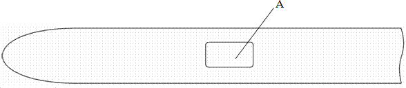
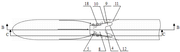
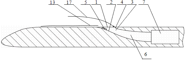
[0013] see Figure 2 to Figure 4 As shown, the present invention discloses a buried air intake adopting a combined oral surface vortex control method, including an air intake inlet 1, a diversion surface 2, a side wall 3, a rear lip 4, and a Some miniature vortex generators 5 on the surface 2, passages 6 in the air inlet. The passage in the air inlet communicates with the turbine engine 7 on the aircraft. The air inlet 1 includes a main inlet 8 located at the front of the entire air inlet 1 and a pair of overflow grooves 9 extending backward from both sides of the rear of the main inlet 8 . The edges 10 on both sides of the inlet 1 of the inlet are expanded, so that the width of the inlet 1 of the inlet gradually increases from front to back, so that a strong main vortex 11 of intake air on the orifice can be generated during intake. . The front end of the rear lip 4 is located between the two overflow grooves 9 and separates the two overflow grooves 9; match. The main in...


PUM


Abstract

The invention discloses an embedded type air inlet channel using a combined opening surface vortex control method. The embedded type air inlet channel comprises an air inlet channel inlet, a flow guide surface, a side wall, a rear lip opening and multiple micro vortex generators, wherein the micro vortex generators are arranged on the flow guide surface; the air inlet channel inlet comprises a main inlet and a pair of overflow grooves; and the main inlet is arranged at the front part of the air inlet channel inlet and the overflow grooves extend backwards from two sides of the rear of the main inlet. The air intake strengthening function of the opening surface main vortex of the embedded type air inlet channel is used; directly flowed secondary vortexes, which continuously expand to two sides of the air inlet channel inlet, are generated by the vortex generators, and main vortexes at two sides of the air inlet channel inlet are thrust to the outside of the inlet, so that most of vortex air flow is exhausted to the outside of the air inlet channel through the pair of overflow grooves at the rear end of the inlet; and besides, at the time, the advantage of the embedded type air inlet channel is realized, the adverse pneumatic impact caused by the main vortex is ingeniously avoided, so that the purposes of increasing the total pressure recovery coefficient of the embedded air inlet channel, reducing the distortion index and improving air intake capability are achieved.

Description

technical field [0001] The invention relates to the field of aircraft design, in particular to a buried air intake. Background technique [0002] The buried air intake is a special subsonic air intake with the inlet buried in the fuselage or wing without any protruding parts. Because of its low wind resistance, good stealth performance, convenient box launch and maintenance and many other advantages, it has received extensive attention from researchers at home and abroad, and has been used as a propulsion system on many foreign aircraft models. The main air intake is used. Such as figure 1 As shown, an existing air inlet A is shown as a rectangular embedded air inlet. Since the existing buried air inlet cannot be provided with a boundary layer partition, a large amount of airflow in the boundary layer of the body is entrained into the inner passage. The pressure recovery coefficient is low and the flow field distortion index is high. At the same time, the buried air int...

Claims


Application Information

Patent Timeline
Patent Type & Authority Applications(China)
IPC IPC(8): F02C7/04
Inventor 谭慧俊孙姝张悦陈昊李光胜
Owner NANJING UNIV OF AERONAUTICS & ASTRONAUTICS
Why Eureka
Try Eureka