A subsonic air inlet integrated with aircraft without partition

An air intake and aircraft technology, which is applied to the combustion of the air intake of the power unit, aircraft parts, and power units on the aircraft, etc., can solve problems such as the disadvantage of the electromagnetic stealth performance of the aircraft, and achieve improved radar stealth performance and low flow field distortion. Exponential, the effect of reducing aerodynamic drag

Inactive Publication Date: 2018-08-31
NANJING UNIV OF AERONAUTICS & ASTRONAUTICS
View PDF5 Cites 0 Cited by
  • Summary
  • Abstract
  • Description
  • Claims
  • Application Information

AI Technical Summary

Problems solved by technology

However, the function of the bulge is different when the boundary-layer separated inlet works at supersonic and subsonic speeds: at supersonic speed, an important function of the bulge is to generate shock waves at the leading edge of the bulge, and to communicate with the The airway lips work together to ensure higher flow capture and form a pressure distribution on the surface of the dome that is high in the middle and low on both sides, thereby displacing the boundary layer to both sides; at subsonic speeds, the dome does not need to generate shock waves , at the same time, the flow capture (discharge coefficient) of the inlet is mainly affected by the design value of the inlet area and the back pressure at the outlet of the inlet. Therefore, the main function of the bulge is to displace the boundary layer. Although compared with the boundary layer, The bulge has greatly reduced the aerodynamic drag and reduced the radar scattering area, but the bulge protruding from the surface of the fuselage is still detrimental to the electromagnetic stealth performance of the aircraft

Method used


Image

  • A subsonic air inlet integrated with aircraft without partition
  • A subsonic air inlet integrated with aircraft without partition
  • A subsonic air inlet integrated with aircraft without partition

Examples


Embodiment Construction

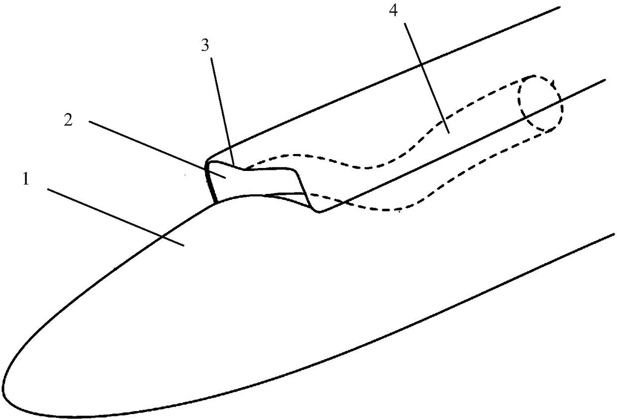
[0016] see Figure 1 to Figure 6 , the invention discloses a non-separated subsonic air inlet integrated with an aircraft considering electromagnetic stealth.

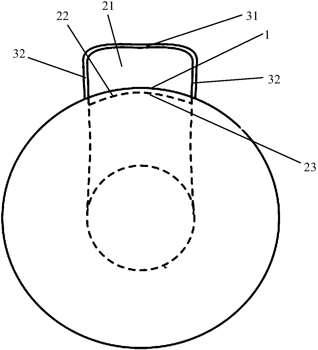
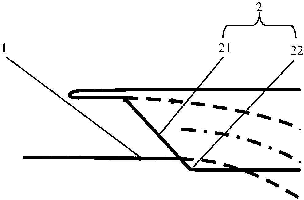
[0017] Please combine figure 1 , figure 2 , image 3 As shown, the non-separated subsonic inlet includes an air inlet surface 2 located at the front end of the air inlet, an air inlet inner channel 4 extending backward from the air inlet surface 2, a lip cover 3 surrounding the air inlet surface, Fuselage section 1 connected to the inlet face. The air inlet surface 2 includes a first opening surface 21 outside the fuselage part 1 and a second opening surface 22 inside the fuselage part 1 . Through the air inlet surface 2 jointly formed by the first surface 21 and the second surface 22, the inlet surface 2 and the fuselage 1 can achieve the effect of integration, that is, the inlet surface 2, especially the second surface 22 The molding line 23 at the fuselage fusion part is blocked by the fuselage part 1 from the...


PUM


Abstract

The invention provides a diverterless subsonic air inlet passage integrated with an aircraft. The diverterless subsonic air inlet passage comprises a lip cover on the basis of electromagnetic stealth and pneumatic consideration and a fully shielded inner pipeline. The shape of an air inlet passage opening surface and a fuselage are in integrated combination designs, and boundary layers at the fronts of inlets can be eliminated by pressure gradients formed by the lip cover and the surface of the fuselage. The lip cover is in sweepback designs in the overlooking and side-looking directions, and sweepback angles are consistent with preset stealth angles of the aircraft. The inner pipeline with an air inlet passage is provided with a selected fully shielded double-S bending type air inlet passage, and the cross sections of outlets of the air inlet passage cannot be seen from optional angles of air inlets. The diverterless subsonic air inlet passage has the advantages that specific bumps, which are protruded on the surfaces of existing fuselages, of conventional diverterless air inlet passages and boundary layer diverters on the existing fuselages can be omitted on the premise that requirements on total pressure recovery coefficients and flow field distortion indexes of the air inlet passage are met, and accordingly pneumatic resistance of the aircraft can be lowered; the radar stealth performance of the air inlet passage can be enhanced under the joint effect of the aircraft, the sweepback lip cover and the fully shielded inner pipeline.

Description

technical field [0001] The invention relates to the field of aircraft design, in particular to a subsonic air inlet. Background technique [0002] Subsonic aircraft is the most common and widely used type of air-breathing aircraft. The inlets of its power system generally have pitot-type inlets, S-curved inlets, buried inlets, etc. . Considering factors such as engine installation and inlet performance, most modern advanced subsonic aircraft use S-curved inlets. [0003] The traditional S-bend air intake usually lifts the air intake inlet away from the fuselage surface by setting special boundary layer partitions and baffles, so as to avoid inhaling the low-energy airflow in the boundary layer of the fuselage surface. Obviously, because the boundary layer partition increases the windward area of ​​the aircraft and forms a corner reflector for radar waves, the aerodynamic resistance of the aircraft will increase and the radar stealth performance will decrease, and the weigh...

Claims


Application Information

Patent Timeline
Patent Type & Authority Patents(China)
IPC IPC(8): B64D33/02
CPCB64D33/02B64D2033/0226B64D2033/0253
Inventor 李博谭慧俊王成吕凌英蔡明轩
Owner NANJING UNIV OF AERONAUTICS & ASTRONAUTICS
Why Eureka
Try Eureka