Low External Resistance Hyper/Hypersonic Inlet and Shock/Boundary Layer Interference Control Method

A hypersonic and air inlet technology, which is applied in the direction of engine control, jet propulsion device, gas turbine device, etc., can solve the problems of limited bulge control effect, large additional deflation resistance, and heavy thermal protection burden, etc., to broaden the working range, The effect of increasing the total pressure recovery coefficient and reducing the drag of the aircraft

Active Publication Date: 2018-05-18
NANJING UNIV OF AERONAUTICS & ASTRONAUTICS
View PDF6 Cites 0 Cited by
  • Summary
  • Abstract
  • Description
  • Claims
  • Application Information

AI Technical Summary

Problems solved by technology

However, although such conventional control methods can achieve certain control effects, there are also obvious deficiencies.
For example, the method of venting through slots realizes the control of flow separation by releasing a large amount of low-energy flow in the boundary layer, and at the same time brings problems such as large additional venting resistance, heavy thermal protection burden, and loss of captured flow; the installation of vortex generators The control ability of the control method is relatively weak, and the structure of the vortex generator itself is relatively fragile, and it is easily damaged under the impact of high-speed airflow. At the same time, there is ablation problem at a high Mach number; The pressure effect and acceleration effect can effectively control the boundary layer separation that occurs on the convex outer surface of the bulge, but when the shock wave / boundary layer interference occurs on the concave inner surface of the bulge, the control effect of the bulge is relatively limited

Method used


Image

  • Low External Resistance Hyper/Hypersonic Inlet and Shock/Boundary Layer Interference Control Method
  • Low External Resistance Hyper/Hypersonic Inlet and Shock/Boundary Layer Interference Control Method
  • Low External Resistance Hyper/Hypersonic Inlet and Shock/Boundary Layer Interference Control Method

Examples


Embodiment Construction

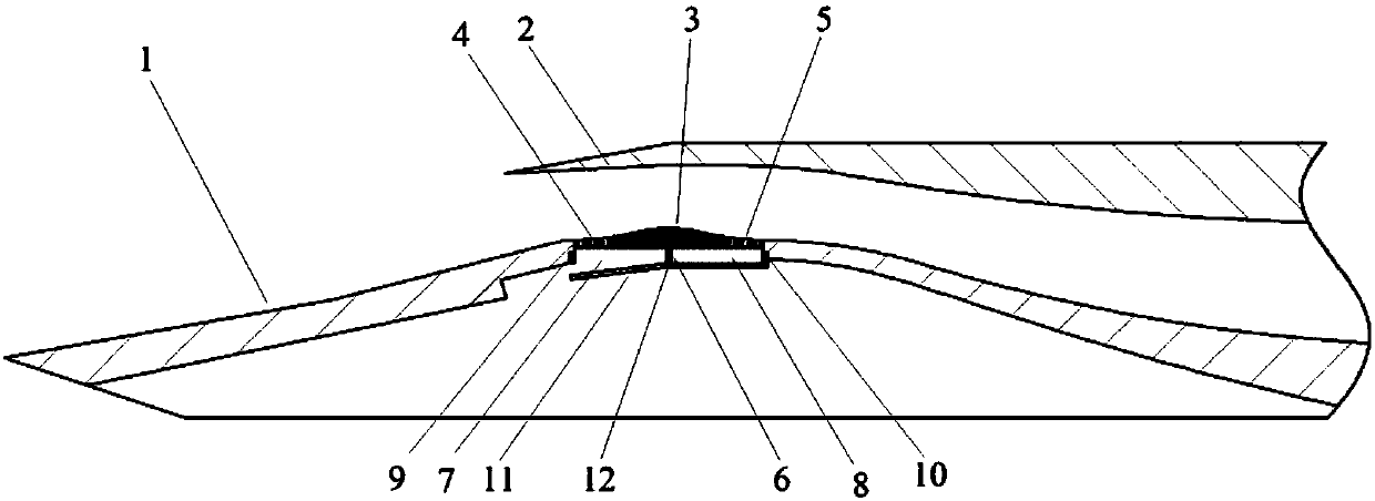
[0021] see figure 1 , the invention discloses a low external resistance super / hypersonic air intake, comprising a precursor compression surface 1, an air intake lip 2, and a two-dimensional protruding into the air intake is arranged on the lower wall surface of the air intake entrance. The wall surface bulge 3, the inner concave section of the two-dimensional wall surface bulge 3 is provided with the front air release slot / hole array 4, and the inner concave section of the two-dimensional wall surface bulge leeward surface is provided with the rear air release slot / hole array 5; The bottom of the two-dimensional wall surface bulge 3 is designed with a deflation cavity and a partition 6 located in the deflation cavity. The downstream deflation sub-cavity 8 below the rear deflation slot / hole array 5, the front wall of the upstream deflation sub-cavity 7 is provided with a front electromagnet 9, and the rear wall of the downstream deflation sub-cavity 8 is provided with a rear el...


PUM


Abstract

The invention provides a low-external-resistance supersonic / hypersonic speed inlet. A two-dimensional bump is arranged at an inlet of the supersonic / hypersonic speed inlet, and partial air discharge seam / hole arrays are arranged at the inward concave positions of the windward side and the leeward side; and meanwhile, an air discharge cavity below the bump is divided into two sub-cavities, and electromagnets and a metal plate with a folded corner are adopted for achieving control over opening and closing of the two air discharge sub-cavities. By means of control over opening and closing of the two air discharge sub-cavities, the low-external-resistance supersonic / hypersonic speed inlet can adapt to shock wave intensity and incidence point position changes brought by inlet working mach number and attitude angle changes, the optimal control ability on boundary layer separation caused by shock wave / boundary layer disturbance of a lip cover is obtained, and the remarkable effects of widening the working range of the low-external-resistance supersonic / hypersonic speed inlet and increasing the total pressure recovery coefficient are achieved. Due to the high flowing control ability of the low-external-resistance supersonic / hypersonic speed inlet, the inlet is allowed to adopt the design of the horizontal lip cover, and therefore the external pneumatic resistance of an aircraft can be effectively reduced.

Description

technical field [0001] The invention relates to the technical field of flow control of high-speed aircraft, in particular to a low external resistance supersonic and hypersonic inlet design. [0002] The present invention also provides a wide-area control method for the lip shock wave / boundary layer interference of the air inlet. Background technique [0003] The phenomenon of oblique shock / boundary layer interference widely exists in the inlet of supersonic and hypersonic aircraft, especially the lip shock / boundary layer interference at the mouth of the inlet, and the separation of the boundary layer air flow at the inlet is It is a prominent problem in the flow organization of the channel in the intake port. It not only leads to a significant loss of total pressure, but also greatly reduces the anti-backpressure capability of the intake port. In the starting state, the available working envelope of the intake port is reduced. This problem is especially obvious in superso...

Claims


Application Information

Patent Timeline
Patent Type & Authority Patents(China)
IPC IPC(8): F02C7/042F02C7/057
CPCF02C7/042F02C7/057F05D2270/17
Inventor 张悦谭慧俊陈昊吕凌英满延进任志文郭赟杰凌棫
Owner NANJING UNIV OF AERONAUTICS & ASTRONAUTICS
Why Eureka
Try Eureka