A longitudinal vortex co-generation heat transfer element

A heat transfer element and longitudinal eddy current technology, which is applied in heat exchange equipment, heat exchanger shells, lighting and heating equipment, etc. Field structure, the effect of strengthening heat transfer

Active Publication Date: 2016-03-30
GUANGZHOU INST OF ENERGY CONVERSION - CHINESE ACAD OF SCI
View PDF8 Cites 0 Cited by
  • Summary
  • Abstract
  • Description
  • Claims
  • Application Information

AI Technical Summary

Problems solved by technology

[0006] In order to overcome or make up for the deficiencies of the above-mentioned heat transfer elements and their enhanced heat transfer mechanism, the present invention provides a longitudinal eddy current synergistic heat transfer element, which solves the problem that the existing heat transfer elements are too large in the tube while enhancing heat transfer. The problem of increased resistance

Method used


Image

  • A longitudinal vortex co-generation heat transfer element
  • A longitudinal vortex co-generation heat transfer element
  • A longitudinal vortex co-generation heat transfer element

Examples


Embodiment Construction

[0022] The present invention is further described below in conjunction with embodiment.

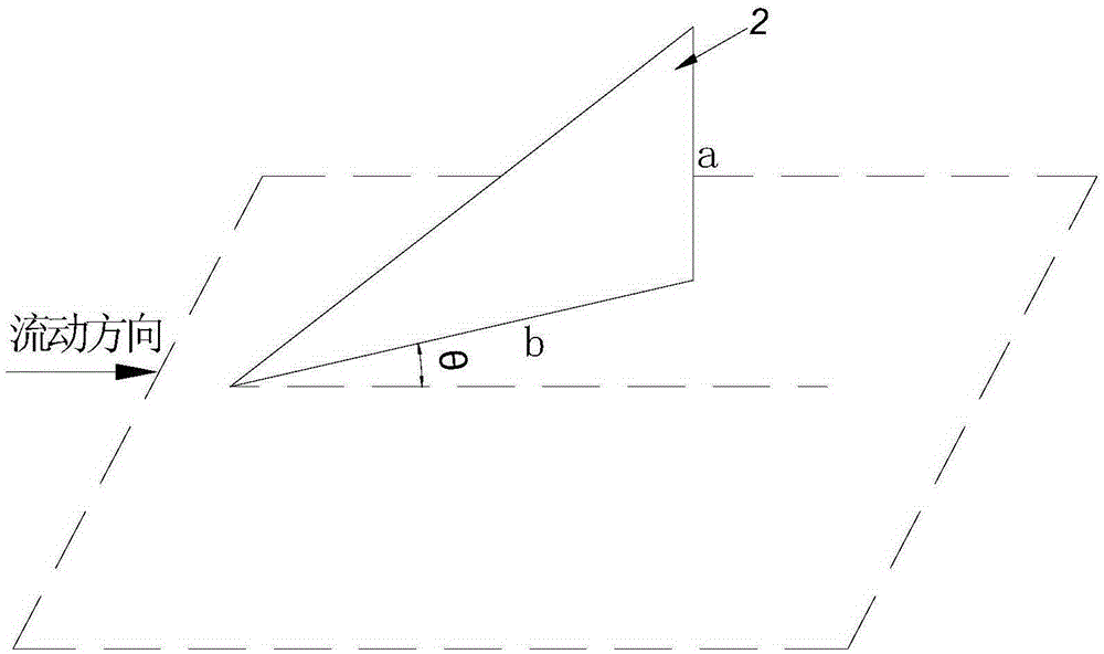
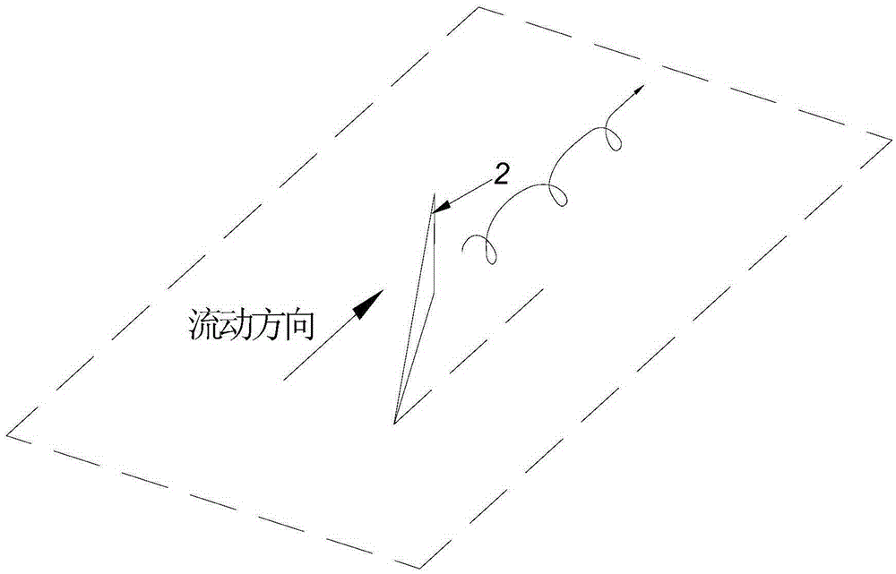
[0023] The structure of the spoiler is as figure 1 As shown, the right-angled side a of the spoiler is perpendicular to the central axis of the metal pipe, and a certain angle θ is formed between the right-angled side b and the central axis. After the fluid passes through the spoiler, a longitudinal vortex is formed in a certain range at the tail of the spoiler, such as figure 2 shown. When the spoiler is deflected to the left of the flow direction, the velocity vector of the longitudinal vortex on the cross section is clockwise, otherwise it is counterclockwise. The strength of the longitudinal vortex is determined by the size of the right-angled side a and b of the spoiler and the deflection angle θ. According to the experimental results, when a / b=0.5 and θ=30°, the strength of the longitudinal vortex is better.

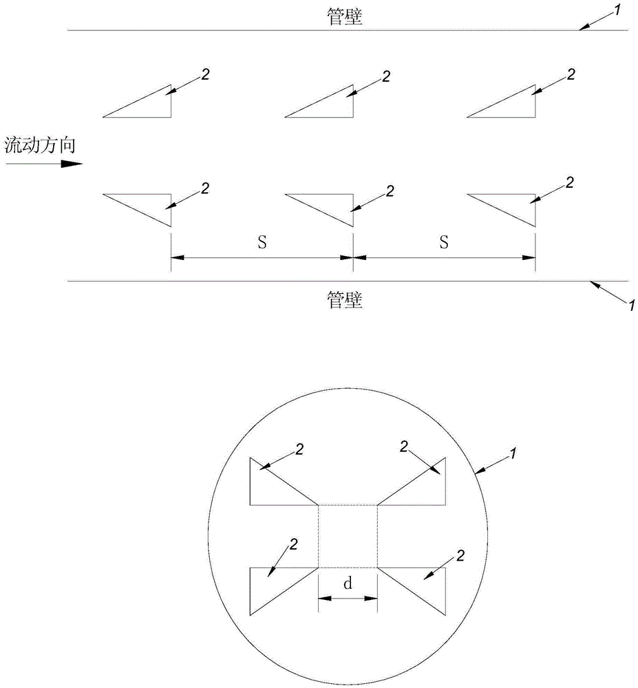
[0024] Put the spoiler set in accordance with image 3 As shown, the...


PUM


Abstract

The invention discloses a longitudinal vortex synergistic-action heat transmission element. The longitudinal vortex synergistic-action heat transmission element comprises a metal pipe and further comprises a plurality of spoiler sets, wherein each spoiler set comprises a plurality of spoilers which are even in number and of a right-triangle structure; the spoilers in the same spoiler set are distributed in a central symmetry and axial symmetry mode with respect to the central axis of the metal pipe; the top points of acute angles of the right-angle sides b of the spoilers in the same spoiler set are located on the same vertical plane, the right-angle sides a of the spoilers in the same spoiler set are perpendicular to the central axis of the metal pipe, and a certain deviation angle theta is formed between the right-angle side b of each spoiler and the central axis of the metal pipe; the spoiler sets are distributed in the metal pipe along the central axis of the metal pipe with a certain separation distance. According to the longitudinal vortex synergistic-action heat transmission element, by means of the spoiler sets in the metal pipe, speed vector synergistic match on the cross section of longitudinal vortexes generated in a heat transmission pipe can be achieved, a flow field structure is optimized, heat exchange is enhanced, and meanwhile increase of flow resistance in the metal pipe is effectively reduced.

Description

technical field [0001] The invention relates to a heat transfer element, in particular to a longitudinal vortex co-generation heat transfer element. Background technique [0002] At present, the components used to enhance heat exchange in tubes mainly include fins, longitudinal vortex generators, helical twisted belts, coiled filaments, spiral coils, and coil springs. Mixing, reducing the thickness of the boundary layer, increasing the heat transfer area, etc. [0003] For example, a discontinuous staggered internal rib enhanced heat exchange tube disclosed in the patent document with the authorized announcement number CN2745021Y is characterized in that: the distribution of the inner wall of the tube is discontinuous, the protruding inner ribs are staggered along the axial direction, and parallel to the axis, The cross-section of the raised inner rib is square, rectangular, trapezoidal, arc-shaped or triangular. The height of the discontinuous raised inner rib is 0.05D-0.2...

Claims


Application Information

Patent Timeline
Patent Type & Authority Patents(China)
IPC IPC(8): F28F9/24
Inventor 郭剑蒋方明
Owner GUANGZHOU INST OF ENERGY CONVERSION - CHINESE ACAD OF SCI
Why Eureka
Try Eureka