Supercharge Your Innovation With Domain-Expert AI Agents!

Linear ultrasonic motor clamping positioning device with one end supported in hinged mode

A linear ultrasonic motor, clamping and positioning technology, applied in piezoelectric effect/electrostrictive or magnetostrictive motors, generators/motors, electrical components, etc., can solve problems such as large tangential stiffness

Inactive Publication Date: 2014-07-23
NANJING UNIV OF AERONAUTICS & ASTRONAUTICS
View PDF12 Cites 10 Cited by
  • Summary
  • Abstract
  • Description
  • Claims
  • Application Information

AI Technical Summary

Problems solved by technology

This kind of linear ultrasonic motor stator with clamping positioning has only one degree of freedom, so when the support point at the head end is close to the mover, the driving foot can only move in the direction perpendicular to the mover’s motion (also called the normal direction), so The tangential stiffness of its orientation is infinite, which maximizes the thrust of the motor

Method used


Image

  • Linear ultrasonic motor clamping positioning device with one end supported in hinged mode
  • Linear ultrasonic motor clamping positioning device with one end supported in hinged mode
  • Linear ultrasonic motor clamping positioning device with one end supported in hinged mode

Examples


Embodiment 1

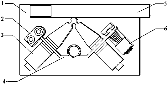
[0023] The utility model relates to a linear ultrasonic motor clamping and positioning device hinged at one end, which belongs to the technical field of ultrasonic motors. Such as figure 1 As shown, the device is composed of a base 1 , a V-shaped stator 3 , a mover 5 , and clamping components, wherein the clamping components include: a rotating device 2 , a support 4 and a pre-pressure applying device 6 .

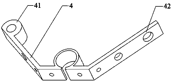
[0024] This new type of clamping and positioning device, such as figure 1 As shown, there is only one degree of freedom for rotation centered on the head end 41 of the support member, and the prepressure loading of the stator 3 on the mover 5 is realized by applying pressure to the force end 42 of the support member by the preload applying device 6 .

[0025] This clamping and positioning device for a linear ultrasonic motor hinged at one end is used for clamping and positioning a V-shaped stator. The V-shaped stator has two vibrators, and each vibrator consists of a front...

Embodiment 2

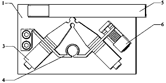
[0031] The invention relates to a clamping and positioning device of a linear ultrasonic motor with a flexible hinge at one end, which belongs to the technical field of ultrasonic motors. Such as figure 2 As shown, the device is composed of a base 1 , a stator 3 , a mover 5 , and clamping components 4 and 6 , wherein the clamping components include: a support 4 and a pre-pressure applying device 6 .

[0032] This new type of clamping and positioning device, such as figure 2 As shown, the position centered on the head end 41 of the support is fixed, and the pressure is applied to the force end 42 of the support by the pre-pressure applying device 6, and the flexible hinge 43 of the support is pushed to deform on the plane where the stator is located to realize the stator 3 pairs. Preloading of mover 5.

[0033] This clamping and positioning device of a linear ultrasonic motor with a flexible hinge at one end is used for clamping and positioning a V-shaped stator. The V-shap...


PUM


Abstract

The invention discloses a linear ultrasonic motor clamping positioning device with one end supported in a hinged mode, and belongs to the technical field of ultrasonic motors. The clamping positioning device is composed of a stator supporting part (4) and a positioning device, the stator supporting part (4) comprises a first supporting arm and a second supporting arm, the end of the first supporting arm serves as a supporting part head end (41), and the end of the second supporting arm serves as a supporting part stressing end (42). The clamping positioning device applies a force on the supporting part stressing end (42) through a pre-compression applying device (6) to enable a motor to rotate around the supporting part head end (41) so as to achieve the purpose that a stator (3) of the motor applies pre-compression on a rotor (5). Due to use of the clamping positioning device, the vibration performance and the structural stability of the ultrasonic motors can be improved further, output force of the ultrasonic motors is improved, and the output efficiency of the ultrasonic motors is increased.

Description

technical field [0001] The invention relates to an assembly and clamping technology of a novel linear ultrasonic motor, which belongs to the technical field of ultrasonic motors. Background technique: [0002] The linear ultrasonic motor is a new type of micro-motor developed and applied rapidly in the 1980s. It uses the inverse piezoelectric effect of the piezoelectric element and the ultrasonic vibration of the elastic body, and through the friction between the stator and the mover, the elastic The micro-vibration of the body is converted into the macroscopic linear (rotational) motion of the mover, which directly pushes the load. It has the advantages of compact structure, high torque at low speed, fast response, high positioning accuracy and electromagnetic compatibility. It has broad application prospects in aerospace, weapon equipment and precision drive fields. [0003] At present, research on linear ultrasonic motors in China is developing rapidly. Universities...

Claims


Application Information

Patent Timeline
IPC IPC(8): H02N2/04
Inventor 姚志远刘振简月
Owner NANJING UNIV OF AERONAUTICS & ASTRONAUTICS
Features
  • R&D
  • Intellectual Property
  • Life Sciences
  • Materials
  • Tech Scout
  • Unparalleled Data Quality
  • Higher Quality Content
  • 60% Fewer Hallucinations
Learn More